| 8. |
CrossarmsñHorizontal Loads |
|
Power Circuits |
|
The point of maximum bending moment will be at the crossarm through bolt attaching the arm to the pole, at which point the cross section of the arm is reduced by the amount of the bolt hole. Crossarms supporting the 60 kV wires are to be Douglas fir, dense, dimensions 4ñ3/4î x 5ñ3/4î x 12í, bored as illustrated below.
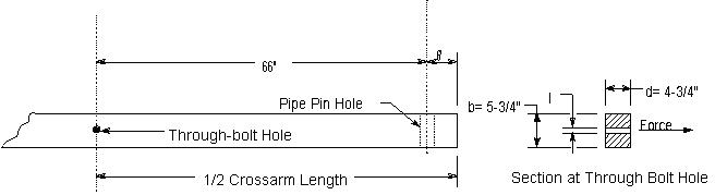
The section through the arm and the method of computing the fiber stress is shown below.0
Longñtime loading: Since longitudinal conductor loads are normally balanced, longñtime horizontal loading of the power circuit crossarms need not be considered.
Single arm, Maximum loading, 25∞F and an 8 lb wind
|
|
|
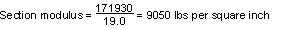
Bending moment = 2,605 x 66 = 171,930 poundñinches |
|
|
|
 |
|
|
|
|
b = 5.75î ñ 0.69 = 5.06î
d = 4.75î
s = 11/16î = 0.69î |
|
|
|
Fiber Stress = Bending moment divided by
|
|
As the allowable value for modulus of rupture in bending under maximum loading conditions is 6,300 lbs per sq. in. (see Table 5 , Rule 48.1 ), a single crossarm of the size chosen provides a safety factor of only 0.70 for the assumed load at maximum loading conditions, whereas the provisions of Rule 47.5 require a safety factor of unity. Double arms will, therefore, be used in this problem to meet the strength requirements applicable to crossarms at end supports of crossings. Double crossarm
construction of this type with separation maintained by space bolts is assumed to have a horizontal strength equivalent to 130% of the sum of the strengths of two single crossarms acting independently.
Maximum loading, 25∞F and an 8 lb wind |
|
|
Bending moment = 2,605 x 66 = 171,930 poundñinches
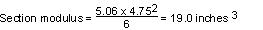
Single arm section modulus (same as previously calculated) = 19.0 inches
Double arm section modulus = 19.0 x 2 x 1.3 = 49.4 inches
|
|
|
|
 |
|
As the allowable modulus of rupture for shortñtime loading is 6,300 lbs per sq. in. then the double crossarms under these conditions will provide a safety factor of 1.91, which meets the unity safety factor required by Rule 47.5. |
|
Private Communication Circuit |
|
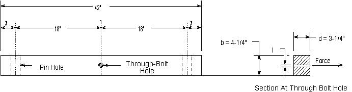
At the crossing span, double crossarms are used on account of deadñend construction due to change of conductor size. Current practice provides for this method of construction although a singlearm has sufficient strength as is found form the following calculations of modulus of rupture under the two limiting conditions of loading:
Longñtime loading, 60∞F and no wind
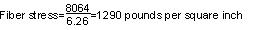
Bending moment = 448 x 18 = 8,064 poundñinches |
|
|
 |
|
|
|
|
b = 5.75î ñ 0.69 = 5.06î
d = 4.75î
s = 11/16î = 0.69î |
|
|
 |
|
The allowable value for modulus of rupture in bending is 0.55 x 6,300 = 4,465 pounds per square inch and therefore with a single arm the factor of safety under conditions of longñtime loading is 2.69.
Maximum Loading
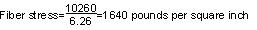
Bending moment = 570 x 18 = 10,260 poundñinches
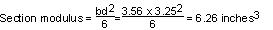
Section modulus = 6.26 inches3 (as per calculations above) |
|
|
 |
|
The allowable value for modulus of rupture in bending, under maximum loading conditions, is 6,300 pounds per sq. in., therefore a single arm provides a safety factor of 3.84 under these maximum loading conditions. |
| 8. |
CrossarmsñHorizontal Loads |
|
Power Circuits |
|
The point of maximum bending moment will be at the crossarm through bolt attaching the arm to the pole, at which point the cross section of the arm is reduced by the amount of the bolt hole. Crossarms supporting the 60 kV wires are to be Douglas fir, dense, dimensions 4ñ3/4î x 5ñ3/4î x 12í, bored as illustrated below.
The section through the arm and the method of computing the fiber stress is shown below.0
Longñtime loading: Since longitudinal conductor loads are normally balanced, longñtime horizontal loading of the power circuit crossarms need not be considered.
Single arm, Maximum loading, 25∞F and an 8 lb wind
|
|
|
Bending moment = 2,605 x 66 = 171,930 poundñinches |
|
|
|
|
|
|
|
|
b = 5.75î ñ 0.69 = 5.06î
d = 4.75î
s = 11/16î = 0.69î
|
|
|
|
Fiber Stress = Bending moment divided by
|
|
As the allowable value for modulus of rupture in bending under maximum loading conditions is 6,300 lbs per sq. in. (see Table 5 , Rule 48.1 ), a single crossarm of the size chosen provides a safety factor of only 0.70 for the assumed load at maximum loading conditions, whereas the provisions of Rule 47.547.3 require a safety factor of unity. Double arms will, therefore, be used in this problem to meet the strength requirementsapplicable
to crossarms at end supports of crossings. Double crossarm
construction of this type with separation maintained by space bolts is assumed to have a horizontal strength equivalent to 130% of the sum of the strengths of two single crossarms acting independently.
Maximum loading, 25∞F and an 8 lb wind
|
|
|
Bending moment = 2,605 x 66 = 171,930 poundñinches
Single arm section modulus (same as previously calculated) = 19.0 inches
Double arm section modulus = 19.0 x 2 x 1.3 = 49.4 inches
|
|
|
|
|
|
As the allowable modulus of rupture for shortñtime loading is 6,300 lbs per sq. in. then the double crossarms under these conditions will provide a safety factor of 1.91, which meets the unity safety factor required by Rule 47.547.3.
|
|
Private Communication Circuit |
|
At the crossing span, double crossarms are used on account of deadñend construction due to change of conductor size. Current practice provides for this method of construction although a singlearm has sufficient strength as is found form the following calculations of modulus of rupture under the two limiting conditions of loading:
Longñtime loading, 60∞F and no wind
Bending moment = 448 x 18 = 8,064 poundñinches
|
|
|
|
|
|
|
|
b = 5.75î ñ 0.69 = 5.06î
d = 4.75î
s = 11/16î = 0.69î
|
|
|
|
|
The allowable value for modulus of rupture in bending is 0.55 x 6,300 = 4,465 pounds per square inch and therefore with a single arm the factor of safety under conditions of longñtime loading is 2.69.
Maximum Loading
Bending moment = 570 x 18 = 10,260 poundñinches
Section modulus = 6.26 inches3 (as per calculations above)
|
|
|
|
|
The allowable value for modulus of rupture in bending, under maximum loading conditions, is 6,300 pounds per sq. in., therefore a single arm provides a safety factor of 3.84 under these maximum loading conditions. |
| 8. |
CrossarmsñHorizontal Loads |
|
Power Circuits |
|
The point of maximum bending moment will be at the crossarm through bolt attaching the arm to the pole, at which point the cross section of the arm is reduced by the amount of the bolt hole. Crossarms supporting the 60 kV wires are to be Douglas fir, dense, dimensions 4ñ3/4î x 5ñ3/4î x 12í, bored as illustrated below.
The section through the arm and the method of computing the fiber stress is shown below.0
Longñtime loading: Since longitudinal conductor loads are normally balanced, longñtime horizontal loading of the power circuit crossarms need not be considered.
Single arm, Maximum loading, 25∞F and an 8 lb wind
|
|
|
Bending moment = 2,605 x 66 = 171,930 poundñinches |
|
|
|
|
|
|
|
|
b = 5.75î ñ 0.69 = 5.06î
d = 4.75î
s = 11/16î = 0.69î
|
|
|
|
Fiber Stress = Bending moment divided by
|
|
As the allowable value for modulus of rupture in bending under maximum loading conditions is 6,300 lbs per sq. in. (see Table 5, Rule 48.1), a single crossarm of the size chosen provides a safety factor of only 0.70 for the assumed load at maximum loading conditions,
whereas the provisions of Rule 47.3 require a safety factor of unity. Double arms will, therefore, be used in this problem to meet
the strength
requirements applicable to crossarms at end supports of crossings. Double
crossarm construction of this type with separation maintained by space bolts is assumed to have a horizontal strength equivalent to 130% of the sum of the strengths of two single crossarms acting independently.
Maximum loading, 25∞F and an 8 lb wind
|
|
|
Bending moment = 2,605 x 66 = 171,930 poundñinches
Single arm section modulus (same as previously calculated) = 19.0 inches
Double arm section modulus = 19.0 x 2 x 1.3 = 49.4 inches
|
|
|
|
|
|
As the allowable modulus of rupture for shortñtime loading is 6,300 lbs per sq. in. then the double crossarms under these conditions will provide a safety factor of 1.91, which meets the unity safety factor required by Rule 47.3.
|
|
Private Communication Circuit |
|
At the crossing span, double crossarms are used on account of deadñend construction due to change of conductor size. Current practice provides for this method of construction although a singlearm has sufficient strength as is found form the following calculations of modulus of rupture under the two limiting conditions of loading:
Longñtime loading, 60∞F and no wind
Bending moment = 448 x 18 = 8,064 poundñinches
|
|
|
|
|
|
|
|
b = 5.75î ñ 0.69 = 5.06î
d = 4.75î
s = 11/16î = 0.69î
|
|
|
|
|
The allowable value for modulus of rupture in bending is 0.55 x 6,300 = 4,465 pounds per square inch and therefore with a single arm the factor of safety under conditions of longñtime loading is 2.69.
Maximum Loading
Bending moment = 570 x 18 = 10,260 poundñinches
Section modulus = 6.26 inches3 (as per calculations above)
|
|
|
|
|
The allowable value for modulus of rupture in bending, under maximum loading conditions, is 6,300 pounds per sq. in., therefore a single arm provides a safety factor of 3.84 under these maximum loading conditions. |