General Order 64-A
Appendix
F
Typical Problems
PART 1
Crossing Problem
The crossing diagram and dimensions are shown on the following page. The primary data chosen for the crossing follow:
DATA OF CROSSING.
Number of Circuits, Voltage and Phase. Two 3-phase 60,000-volt circuits. One private telephone circuit.
Configuration. Power conductors of each circuit in vertical plane on opposite ends of the crossarms. Private telephone circuit in horizontal plane.
Conductors. Power circuits-6 No. 00 A.W.G. copper, hard drawn, stranded, bare. *Private telephone circuit-2 No. 8 A.W.G. copper, and 2 No. 6 A.W.G. copper, hard drawn, solid, bare.
* It is assumed that the private telephone circuit on the power line pole is run, operated and maintained consistently, as a communication circuit as defined in Rule 20.5-A, thus Grade �B� construction applies only at the crossing span.
Insulators. Pin Type porcelain, to meet the requirements of the rules.
Ties. Annealed copper wire to meet the requirements of Rule 49.3.
Pins. Power Circuits. Iron (extra strong) 1 ��� (nominal) X 18 ��� � pins of each circuit metallically bonded together to conform to the requirements of Rule 53.4.
Communication Circuits. 1 ��� X 9�� locust pin
Crossarms. Power Circuits. Douglas fir 5 ��� X 5 ��� X 12�-0��, 1.9�� pin holes �11/16�� hole for pole bolt.
Communication Circuits. Douglas fir 3 ��� X 4 ��� X 42��
Crossarm Braces. To conform to Rule 52.9-B
Poles. Western red cedar.
Pole Framing. As per dimensional diagram.
Location of Poles. As per dimensional diagram.
Length of Crossing Span. 200 feet
Length of Adjacent Spans. 150 feet
CONSTRUCTION REQUIREMTNS.
1. Conductor Sags (Normal Conditions, 60�F., no wind).
The required sags of power and telephone conductors are determined from the minimum requirements given in this order. From the curve sheet shown here it is found that the correction factor for apparent sag is negligible and therefore normal sag values as shown below are used.
200 foot span:
#00 A.W.G. copper wire 12 inches
#6 A.W.G. copper wire 13 inches
150 foot span:
#00 A.W.G. copper wire 6.9 inches
#8 A.W.G. copper wire 7.2 inches
2. Conductor Sags (Light Loading 25� F., 8 pounds wind)
Since no ice loading is considered, the vertical sags under the light loading condition will be less than normal sags at 60�F. and no wind. Consequently the clearances provided under light loading will be greater than normal conditions, and it is therefore only necessary to determine the elevations of supports to provide the required clearances under normal conditions, 60�F. and no wind. The tensions in the conductors loaded are found from Tables 15 and 16, Appendix B, to be as follows:
| Copper Conductors |
|
| No 00 A.W.G. hard drawn, stranded, bare |
2,960 lbs. |
| No 8 A.W.G. hard drawn, solid, bare |
640 lbs. |
3. Horizontal Conductor Separation from Center Line of Pole
Table 1, case 7, the following minimum clearances under the most severe conditions apply:
|
|
Minimum |
Used |
| 60,000 volts circuit |
18�� |
5�6�� |
| Communication circuit |
15�� |
18�� |
4. Vertical Conductor Separation.
From Rule 36 modifying the minimum vertical separation as given in Table 2, for conductors of 60,000 volts on the same pole, a minimum of 4 feet is allowed. For this problem a 5�6�� separation is used.
The minimum separation between the supply conductor on the lowest crossarm and the private telephone circuit is given by Table 2, as 6 feet. For this problem an 8 foot separation is used.
5. Clearances of Conductors Above Crossarms.
Table 1, case 9, column F, gives the minimum clearance of conductors in the 60,000 volt class above the supporting crossarms as 9 inches. Since in this case a 18 ��� pin is employed, the clearance of the conductor above the crossarm is 14 inches, which is in excess of the minimum requirements.
6. Vertical Clearance of Conductors Over Highway, Pole lines and Railroad Tracks.
The poles supporting the crossing span are 55 feet in length set 7 feet in the ground. From the dimensions of the pole framing diagram, the distance from the conductors of the private telephone circuit to the ground is 28�4�'. The ground level is given as the same elevation the as top of the rail.
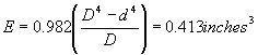
The sag of the signal conductors in the crossing span is given above as 13 inches. The plan on the following page gives the distances from supporting pole C to the various structures crossed over as follows:
Telephone pole line � 37�6��
Highway (center) � 60�0��
Telegraph pole line on R.R r/w � 97�6��
Center railroad tracks � 138�9��
Railroad signal pole line � 180�0��
Total length of crossing span, 200 feet.
In the case of clearances of the private telephone circuit conductors above the crossed over telephone pole lead the following calculations are obtained:
Clearance point distance from C 37�6��
37�6�� = 61% of the center sag.
.61 X 13 = 8.0�� center sag
28�4�� � (8.0�� plus 24�) = 3�8��, clearance
The minimum required clearance, as given in Table 2, would be 2 feet.
In a like manner the clearances of the private telephone circuit conductors at the other points of crossing are as follows:
| Points of Crossing |
Clearance |
Minimum by rules |
| Highway (center) |
27�5�' |
18�0�� |
| Telegraph pole line |
3�3�� |
2�0�� |
| Railroad tracks (center) |
27�5�� |
25�0�� |
| Railroad signal pole line |
5�11�� |
2�0�� |
The clearances of the lower power conductors at the various points of crossing can likewise be computed and are as follows:
| Points of Crossing |
Clearance |
Minimum by rules |
| Telephone pole line |
13�2�� |
8�0�� |
| Highway (center) |
36�11�� |
30�0�� |
| Telegraph pole line |
12�9�� |
8�0�� |
| Railroad tracks (center) |
36�11�� |
34�0�� |
| Railroad signal pole line |
15�5�� |
8�0�� |
7. Insulators.
In addition to the electrical requirements set forth in Rules 55, 104 and 114, the insulators supporting the supply and communication conductors shall have a safety factor (mechanical) of 3 and 2, respectively.
8. Pins, Ties and Conductor Fastenings.
Pins, ties and conductor fastenings used in connection with pin type insulators shall conform to Rule 49.3. In this problem a No. 2 and No. 8 annealed copper wire for the No. 00 and No. 8 circuits involved are used.
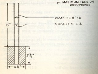
Pins used in connection with pin type insulators shall have sufficient strength to withstand the tension in the conductor. In the case under discussion wrought iron pipe pins are to be employed for the power conductors and locust pins for the private telephone conductors of the dimensions and construction indicated below.
Bending moment (at crossarm) = M = 2960 X 15=44,440 inch-pounds
Moment of
inertia ![]()
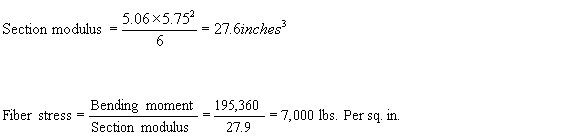
Section modulus
Fiber
stress ![]()
Assume that the ultimate fiber stress for wrought iron is 45,000 pounds per square inch, a single pin is of this type is not sufficient, as it provides a safety factor of 45,000 divided by 107,500 or .418 for an assumed stress of 2960 pounds tension in the conductor.
Since a safety factor of unity is required, double crossarms, pins and insulators are used on the crossing structures.
Locust pins 1 ��� X 9�� are employed for supporting the private telephone conductors except at the dead ends. Since locust pins of these dimensions provide strength up to 1000 pounds tension in the conductor, with the conductor 3 � inches above the crossarm (Rule 49.2-C), and the maximum tension in the conductor is only 320 pounds, the required strength is amply met.
9. Crossarms � Horizontal Load on Cross Arms.
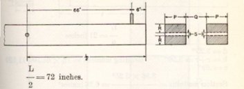
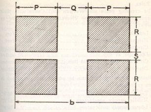
The point of maximum bending moment will be at the cross arm through bolt attaching the arm to the pole, at which point the cross section of the arm is reduced by the amount of the bolt hole. Crossarms supporting the 60 K.V. wires are to be of Douglas Fir, dimensions 5 ��� X 5 ��� 12�, bored as illustrated below:
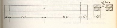
The section through a single arm and the method of computing the fiber stress is shown below.
Bending moment = 2960 X 66 =195,350 inch-pounds
![]() where
where
d=5.75��
R=2.531��
S=0.6875��
B= R plus R=5.06��
As the allowable fiber stress is 6,800 pounds per square inch, a single crossarm of the size chosen provides a safety factor of only 0.97 for the assumed load.
Double arms used in this problem are spaced 8 inches apart, the separation being maintained by space blocks and bolts. Crossarm construction of this type is assumed to have 40 percent of the strength of two crossarms of the same dimensions connected as a rigid truss.
Below is shown a single arm section through a double arm and method of computing the fiber stress.
P=5.75��
Q=8��
B=R+R=5.06��
D3=(P+P+Q)3-Q3=6,903
Bending moment=195,360 inch pounds.
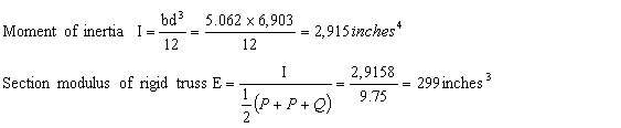
Allowable section modulus = 299 X .40 = 119.6 inches3
![]()
As this represents a safety factor of 4.17, double arms provide ample strength.
At the crossing span double cross arms are used for the communication on account of dead-end construction being employed due to change of conductor size. Current practice provides for this class construction although a single arm has sufficient strength as is found from the following calculations of fiber stress.
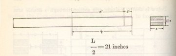
d=3.25��
b=r + r=3.56�� Bending moment 18 X 640=11,520
s=.69��
![]()
Ample strength is provided as a safety factor of 3.69 is obtained, but, conforming to standard practice, double arms are used at this dead end.
10. Crossarms � Vertical Load on Crossarms.
The vertical load on double supply cross arms under maximum conditions of loading will, for the conductor, be equal to the weight per foot of wire (since no ice loading is considered) time one-half the sum of the length of the crossing and adjacent spans plus a dead weight of 200 pounds.
Thus-
![]()
The added weight due to increase of conductor length account of sag and 5 feet difference of elevation of supports is negligible and, accordingly, is not considered. Due to the fact that no recognition of the effects of the crossarm braces is made, no allowances are included for the added weight due to pins, insulators and ties.
Bending moment = 272X 66=17,950 inch pounds.
The fiber stress calculations for the top arm computed below. The stress on the second and third arms decreases for increase of pole diameters, on account of the taper of the pole.
b=P+P+Q S=.69
b=19.50 P=5.75��
Q=8��
R=2.53��
D3=(R+R+S)3-S3
D3=189.7
Moment of
inertia I = ![]()
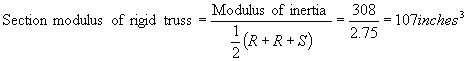
Allowable section modulus = .40 X 107 = 42.8 inches3
![]()
As the allowable fiber stress is 6,800 pounds per square inch, the stress due to the dead load with safety factor of unity is unimportant.
The dead-end load on the telephone double arms, computed in a similar manner, is found to be 171.2 pounds per square inch.
11. Poles
The crossing poles are Western red cedar and their dimensions, considering the clearances required, are as follows:
Length |
55 feet |
Height above ground |
48 feet |
Circumference at top |
28 inches |
Diameter at top |
8.91 inches |
Circumference at Ground Line |
49 inches |
Diameter at Ground Line |
15.6 inches |
Distance from ground line to conductors supported is given as follows:
Top supply conductors |
48�9�� |
Middle supply conductors |
43�3�� |
Lower supply conductors |
37�9�� |
Private telephone conductors No. 8 copper |
28�9�� |
Private telephone conductors No. 6 copper |
28�4�' |
Ground level at base of pole is considered to be at the same elevation as top rail.
Dimensions of adjacent poles B and E are
Length |
50 feet |
Height above ground |
43.5 feet |
Circumference at top |
28 inches |
Diameter at top |
8.91 inches |
Circumference at Ground Line |
47 inches |
Diameter at Ground Line |
14.96 inches |
12. Transverse Load on Poles C and D
The maximum stress on the poles, due to an 8-pound wind on projected areas of pole and conductors, maximum stress assumed at ground line.
The approximate moment at the ground, due to wind pressure on pole, is
![]()
where
P=Pressure in pounds per square foot on projected area of pole
H=Height of Pole above ground
D1=Diameter of pole at ground in inches.
D2=Diameter of pole at top in inches.
The moment at the ground due to wind pressure on the wires is.
![]()
Where:
Ph= |
Horizontal load per lineal foot due to an 8 pound wind pressure on projected area of wire |
L= |
Height of conductors above ground in feet |
n= |
Number of wires |
S1 and S2= |
Length of crossing and adjacent spans, respectively |
Mp= |
Moment due to wind pressure on pole |
Mc0= |
Moment due to pressure on top supply conductors |
Mc1= |
Moment due to pressure on middle supply conductors |
Mc2= |
Moment due to pressure on lower supply conductors |
Mc3= |
Moment due to pressure on telephone conductors |
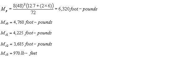
Total Moment =Mp + Mc0 + Mc1 + Mc2+ Mc3
![]()
Moment due to supply wires:
Ph = 0.279 pounds per linear foot for No. 00 A.W.G. copper, stranded, bare
Moment due to telephone conductors:
Ph = 0.085 pounds per linear foot for No. 8 A.W.G. copper, solid, bare
Ph = 0.108 pounds per linear foot for No. 6 A.W.G. copper, solid, bare
Total Mc3= 970 foot pounds
Total Bending Moment = 22,200 pound-feet
![]()
where
M = Moment in Pound-feet
F = Fiber stress in pounds per square inch
D1 = Diameter of pole at ground
![]()
F=713 pounds per square inch
The allowable fiber stress for Western red cedar poles to provide a factor of safety of 4 is 1,250 pounds, hence the crossing poles do not require to be side guyed.
If poles of the minimum dimensions given in Rule 49.1 were employed as is permissible, then
Length |
55 feet |
Height above ground |
48 feet |
Circumference at top |
19 inches |
Diameter at top |
6 inches |
Circumference 6 feet from butt |
38 inches |
Diameter 6 feet from butt |
12.7 inches |
Then,
Total Bending Moment = 19,960 foot-pounds
![]()
F=1,150 pounds per square inch=Fiber Stress.
Thus a pole having a top diameter of 6 inches and a ground line diameter of 12.7 inches will also meet the requirements for transverse load without the use of side guys.
The minimum sized poles thus permitted will also meet the requirements for transverse load without the use of side guys.
13. Side Guying
If side guying were required for poles C and D, the method of figuring same is as follows:
Side guys are figured to take the entire transverse load (between the guyed poles of C and D), the pole acting merely as a strut.
The transverse force acting on the poles will be due to wind pressure on poles C and D and the transverse wind pressure on the conductors supported. The length of conductor used in figuring this transverse force will be equal to one-half the length of the span adjacent to these poles,
Thus,
Supply conductors
![]()
Telephone conductors
![]() ft. for No. 6 A.W.G. bare copper wire
ft. for No. 6 A.W.G. bare copper wire
![]() ft. for No. 8 A.W.G. bare copper wire
ft. for No. 8 A.W.G. bare copper wire
Moment due to wind on pole Mp, = 8,560 pound-feet
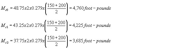
Moment due to conductors |
|
Mc0=48.75 x 2 x 0.279 x 175= |
8,760 ft. lbs. |
Mc1=43.25 x 2 x 0.279 x 175= |
4,225 t. lbs. |
Mc2=37.75 x 2 x 0.279 x 175= |
3,685 ft. lbs. |
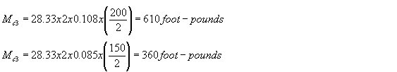
Mc3=28.33 x 2 x 0.085 x 100= |
610 ft. lbs. |
Mc3=28.33 x 2 x 0.085 x 75= |
360 ft. lbs. |
Total Mc3= |
970 ft. lbs. |
Total moment, |
22,200 ft. lbs. |
Center of load ![]()
Center of load = 32.4 feet from ground line,
Where wind load
3(2 X .279 X 175) = 293.00
2 X .108 X 100 = 21.60
2 X .085 X 75 = 12.75
.5 X 48 X 8560 = 357.00
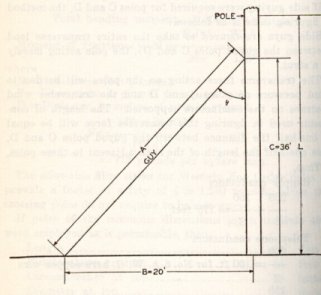
Let Mt = Total moment on pole = 22,220 pound-feet
C=Height of guy attachment from ground = 36 feet (Assumed)
B=Distance of guy anchor from base of pole = 20 feet (Assumed)
T=Tension in guy wire
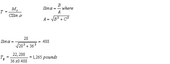
The specified safety factor guys is 2 and, but using one 3/8 inch Siemens-Martin guy strand, adequate strength is obtained.
14. Load on Crossing Poles �C� and �D�.
Rule 47.5 provides that crossing structures shall withstand at all times with a safety factor of unity the unbalanced stress due to the combined pull toward the crossing of one-third of the total number of conductors supported, the pull in each such conductor being taken as the tension due to the specified loading.
No. of
Conductors involved = ![]() Use 3
Use 3
Locations of Conductors:
Two on top arm
One on next arm
2 X 2,960 X 48.75 = 288,500 foot-pounds
1 X 2960 X 43.25 = 128,000 foot-pounds
Total Moment = 416,500 foot-pounds
![]()
The allowable fiber stress under this unbalanced load is 5,000 pounds per square inch, hence poles C and D must be head guyed.
Center of load:
48.75 x 2 x 2,960 =288,500
43.75 x 2 x 2,960 =256,000
37.75 x 2 x 2,960 =223,500
28.33 x 2 x 640 =36,200
Total Moment =804,200 pound-feet
3(2 x 2,960) =17,760 pounds
2 x 640 =1,280 pounds
Wire Tensions =19,040 pounds
![]()
B=150
C=34.
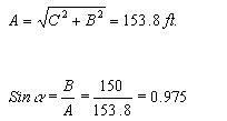
![]()
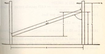
Under a longitudinal stress as above considered, the pole, or, in this case the guy can be figured to withstand this stress with a safety factor of unity; that is the guys can be figured as stressed to their ultimate strength. There will be required, therefore, guys with ultimate strength of 12,580 pounds. The stress may be assumed to be distributed over one or more poles adjacent to the crossing poles. IF so assumed one head guy may be installed on each of the crossing poles C and D and also on each of the adjoining poles B and E.
The stress on poles B and E due to guy attachments 8 feet above the ground follows:
Bending moment=8 x 12,250 = 100,700 foot pounds.
![]()
Pole taper is .437 inches per foot.
![]() \
\
14.96-1.11=13.85inches = Diameter 8 feet from ground line.
As a fiber stress of 5,000 pounds per square inch is required for unity safety factor, no additional guys are required on these poles.