General Order 64-A
Appendix
F
Typical Problems
PART 2
Dead-end Problem
It is the object of this problem to indicate the construction requirements for a typical dead-end structure, since the longitudinal stresses imposed upon such a structure differ substantially from those on a pole on which the conductors supported are normally balanced. The dead-end structure considered herein is assumed to support an 11,000 volt circuit, a 4,000 volt circuit and two secondary circuits. It is also assumed that the dead-end pole takes Grade “A” construction by virtue of its location.
The dead-end structure diagram and dimensions are shown on the following page. The primary data chosen for this structure are as follows:
Data For Dead-end Structure
Supply Conductors
|
11 kV circuit |
3 No.0 A.W.G. Copper H.D. Stranded |
|
4 kV circuit |
4 No.2 A.W.G. Copper H.D. Stranded |
|
120/240 volt circuit |
3 No.4 A.W.G. Copper H.D. Stranded |
|
120/240 volt circuit |
3 No.2 A.W.G. Copper H.D. Stranded |
Insulators - Strain Type (to conform to Rule 49.5).
Conductor fastenings (to meet the requirements of Rule 49.3)
Crossarms:
|
11 kV circuit |
Douglas fir 4–3/4” x 5–3/4” x 10’–0” |
|
4 kV circuit |
Douglas fir 4–3/4” x 4–3/4” x 7’–8” |
|
Secondary circuits |
Douglas fir 4–3/4” x 4–3/4” x 7’–0” |
Crossarm braces (to conform to Rule 49.2-D)
Pole - western red cedar.
Pole dimensions.
55’ in length; 25” top circumference; 50” ground line circumference (ground line diameter 15.9”).
Construction Requirements
1. Conductor Tensions
It is assumed that the conductors are strung with the minimum sags specified in sag curves of Appendix C, hence the tension values are taken from Tables 15 and 16. These values are as follows:
|
No.0 A.W.G. Copper H.D. Stranded=2,375 pounds |
|
|
No.2 A.W.G. Copper H.D. Stranded=1,520 pounds |
|
|
No.4 A.W.G. Copper H.D. Stranded=980 pounds |
|
2. Crossarms
Spacings assumed are shown on the pole framing diagram on the previous page.
Double crossarms of Douglas fir, dense, are employed for each of the 4 different circuits.
The stresses imposed upon the various crossarms by the unbalanced wire loads were computed in the same manner as outlined in Part 1 of this Appendix, except that the tension of all of the conductors carried was considered.
The unit stresses were found to be as follows:
|
Top crossarms |
4 KV Circuits |
2,130 lb. Per sq. inch |
|
Second Crossarms |
4 KV Circuits |
1,660 lb. Per sq. inch |
|
Third crossarms |
Secondaries |
955 lb. Per sq. inch |
|
Fourth crossarms |
Secondaries |
1,385 lb. Per sq. inch |
Since a factor of safety of 2 permits a maximum stress of 3,400 pounds per square inch, the cross arms chosen are satisfactory.
3. Poles.
Rule 44 provides that poles supporting unbalanced longitudinal loads in Grade “A” construction shall have a safety factor of 4 against such loads. Rule 47.3 specifies that guys used to support unbalanced longitudinal loads shall have a safety factor of 2 for all grades of construction (Where guys are used they must take the entire load with the designated safety factor, the pole being considered merely as a strut).
Using the values of tension given in 1, above, the following moments due to dead-end pull, are obtained:
|
3 x 2,375 x 47.3 |
= |
337,000 foot-pounds |
|
4 x 1,520 x 38.3 |
= |
232,800 foot-pounds |
|
3 x 980 x 30.3 |
= |
89,100 foot-pounds |
|
3 x 1,520 x 25.3 |
= |
115,400 foot-pounds |
|
Total Dead-End Moments |
= |
774,300 foot-pounds |
The total dead-end stress, under maximum loading will be, using the tension values given above (in pounds):
|
3 x 2,375 |
= |
7,125 pounds |
|
4 x 1,520 |
= |
6,080 pounds |
|
3 x 980 |
= |
2,940 pounds |
|
3 x 1,520 |
= |
4,560 pounds |
|
Total |
|
20,705 pounds |
![]()
The tension in the guy with a lead over height of 1 to 1 (assumed) and a safety factor of 2 would be:
![]()
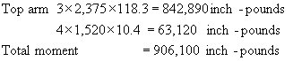
Guys strands attached at the center of load can be used provided the fiber stress of the pole is not exceeded. The stress due to guying at this point would be as follows:
The center point of the load (or a distance of 37.4 feet above the ground) would fall approximately 9.86’ from the top conductors, or about 0.86’ below the second (4 kV cross arm) conductors.
The stress due to bending if guys were attached at this point is as follows: in the pole at the center of load due to the tension in the conductors above the center of load is computed as follows:
The section modulus of a solid circular section is equal to
![]()
The pole at this proposed point of attachment has a diameter of 10.35 inches, hence, the section modulus at this point is therefore,
0.0982 x (10.35)3 = 108.58 inches3
The unit stress would be
![]() pounds per square inch
pounds per square inch
Since a pole, under conditions of unbalanced loads, must provide a safety factor of 4, the stress at points where guys are attached must not exceed 1,250 pounds per square inch. As the above computations show that the fiber stress is exceeded by using guys at center load, three 9/16’’ high strength steel strands are used, as illustrated on the following page.
The foregoing calculations are based on minimum sags of 12 inches at 60 degrees F. for 200 foot spans. By increasing the sags to 18 inches the unbalanced pull would be reduced 1/3. If this increased sag were considered in this problem, it would have been necessary to guy against a horizontal load of 13,665 pounds, instead of 20,705 pounds.