
Original General Order 95
Appendix
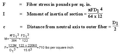
F
Typical Problems
Part I
Crossing Problem
A diagram including dimensions is shown between pages
300 and 301 (page F–18). The data
chosen for the crossing follow:
Data of Crossing
Circuits
Two 3–phase 60,000 Volt power circuits. One metallic private
Class “C” telephone circuit
Configuration
Power conductors of each circuit are in vertical planes
on opposite ends of the crossarm. Private telephone circuit is in a horizontal
plane.
Conductors
Power circuits are six No. 00 AWG, bare, stranded,
hard–drawn copper. Private telephone circuit is two No. 8 AWG, bare, solid,
hard–drawn copper, except in the crossing span where it is two No. 6 AWG,
bare, solid, hardrawn copper.
Insulators
Porcelain, pin type, meeting the requirements
of Rule 49.5–A
.
Ties
Annealed copper wire to comply with
Rules 49.3–B
and 49.3–C
.
Pins
Power circuits–wrought iron
pipe (extra strong), 1–1/2” x 18–1/2”, to comply with Rules
49.3–B
and 49.3-C
. Assumed bonded in accordance with the requirements of
Rule 53.4
.
Communication circuit
- 1–1/2” x 9” locust
Crossarms
Power circuits–Douglas
fir (dense), 4–3/4” x 5–3/4” x 12’, 1.9” pin holes, 11/16” hole for through
bolt.
Communication
circuit–Douglas fir (dense), 3–1/4” x 4–1/4” x 42”, l–l/2” pin holes, 11/16”
hole for through bolt.
Crossarm
Braces
Meeting
the requirements of Rule 49.2–C
.
Poles
Western red cedar, round, butt treated
Span Length
Crossing span, 200 feet.
Adjacent spans, 150 feet
Construction Requirements
1. Conductor Sags and Tensions
The conductors are assumed to be strung so that at normal conditions of
60°F and no wind the tension will be 35% of the ultimate tension of the
conductors. From Chart No. 1, Page 271,
it will be seen that under these conditions the No. 00 AWG conductor, for
a 200 foot span, will have a sag of 1.0 foot (0.99 when calculated), and the
No. 6 AWG conductor will have a sag of 0.90 foot (0.89 when calculated). These
sags may be calculated by means of the following approximation formula:
|
Where |
w = conductor loading, pounds per lineal foot |
|
|
d = span length, feet |
|
|
T = assumed allowable conductor tensions at 60° F and no wind |
For No. 00 AWG conductor
![]()
For No 6 AWG conductor
![]()
Maximum conductor load to be met with a safety factor of not less than 2
as specified in Rule 44.1
will occur at the conditions of 25°F and an 8 pound wind (
Rule 43.2
). Conductors which have been strung at the normal conditions stated above
(60°F, no wind, and 35% ultimate tension) will have sags and tensions
at the maximum loading conditions of 25°F and an 8 pound wind as indicated
below. Maximum conductor sags will occur at the condition of maximum temperature,
130°F and also are shown in the following tabulation:
|
|
#00 AWG |
#6 AWG |
||
|
Sag
(Feet) |
Tension (Pounds) |
Sag
(Feet) |
Tension
(Pounds) |
|
|
Ultimate Conductor Tension (See Appendix B, Table 18) |
- |
5,925 |
- |
1,280 |
|
35% Ultimate at 60°F, No Wind |
0.99 |
2,074 |
0.89 |
448 |
|
25°F, 8 Lb Wind |
0.95 |
2,605 |
1.18 |
570 |
|
130°F, No Wind |
1.78 |
1,157 |
1.55 |
256 |
From the foregoing it will be seen that by stringing the conductors to 35%
of ultimate tension at 60°F and no wind, the safety factor of the conductors
at maximum loading (25°F, 8 lb wind) is somewhat greater than the minimum
of 2 required by Rule 44.1
Lesser sags than those shown above may be used, provided conductor tension,
at maximum loading condition specified in Rule
43 , does not exceed 50% of the ultimate tension of the conductor. The rules,
of course, do not prevent the use of greater sags than are calculated above.
2.
Conductor Clearance from Center Line of Pole
Minimum clearances specified in
Table 1, Case 8
and Rule 54.4–D2
and the clearances assumed for the purposed of this problem are as follows:
|
|
Minimum |
Used |
|
60,000 Volt circuits |
21.5” |
5’ 6” |
|
Communications circuit |
15” |
18” |
3.
Conductor Separation
Table 2, Case 12, Column H
modified by Rule 54.4–C1c
, permits a vertical separation of not less than 36 inches between the conductors
of a 60,000 Volt circuit in vertical configuration. For this problem a separation
of 5’6” is used.
The minimum separation between the level of the lowest supply conductor
and the communication circuit is 72 inches (
Table 2, Case 8, Column H
). For the problem, a separation of 96 inches between crossarm centers is
used.
4.
Clearances of Conductors Above Crossarms
The minimum clearance of a 60,000–volt conductor from the surface of a crossarm is required (by Table 1, Case 9, Column F
) to be at least 1/4 of the pin spacing specified in
Table 2, Case 15, Column H
, which would be a minimum clearance of 9 inches. For this problem, an 18–1/2
inch pin is used which, with its insulator, places the conductor 14 inches
above the crossarm.
5.
Conductor Clearances Above Highway, Pole Lines and
Railroad Tracks
The poles supporting the crossing span are 55 feet in length, set 7 feet
(Rule 49.1-C
) in the ground. From dimensions of the pole framing diagram the distance
of the private telephone circuit above ground is 28’ 4”. For this problem,
a common elevation has been assumed for the ground line, the railroad tracks
and the highway.
The sag of the communication conductors in the crossing span is approximately
11 inches at 60°F and 19 inches at 130° F. Since the allowable variation
of 5% for temperature, applied to the ground clearance of 27’ 5” (28’ 4” -
11”), is 1’ 4”, which is greater than the difference between the sags at 60°F
(11”) and at 130°F (19”), the clearances may be determined at 60°F
for all conditions. In the diagram,
between pages
300 and 301 (page F–18)
, the distances from supporting pole C to the various objects crossed over
by the conductors are as follows:
|
Telephone pole line |
37’ |
6” |
|
Highway (center) |
60’ |
0” |
|
Telegraph pole line on RR r/w |
97’ |
6” |
|
Railroad Tracks (center) |
138’ |
9” |
|
Railroad Signal pole line |
180’ |
0” |
The total length of crossing span is 200 feet. Therefore, the clearance
at 60°F of the private communications circuit above the telephone lead
at point of crossing is obtained as follows:
Clearance point distance from Pole C is 37’ 6”.
At 37’ 6”, or 18.8% of the span, the sag is equivalent to 61% of the center
sag (see Chart No. 9 on Page 279), or 0.61 x 11 = 7” sag.
Therefore, the clearance equals:
28’ 4” - (7” + 24’) = 3’ 9” clearance.
The minimum required clearance as given in
Table 2, Case 3, Column Cis 2 feet.
In a like manner the clearances, at 60°F, of the private communication
circuit conductors at the other points of crossing are as follows:
|
Points of crossing |
Clearances |
Minimum by Rule |
|
Highway (center) |
27’ 7” |
18’ 0” |
|
Telegraph pole line |
3’ 5” |
2’ 0” |
|
Railroad Tracks (center) |
27’ 7” |
25’ 0” |
|
Railroad Signal pole line |
6’ 0” |
2’ 0” |
6. Insulators
In addition to the electrical requirements set forth in Rules
55,
104,
and 114, the insulators supporting the supply and communication conductors shall
have safety factors (mechanical) of 3 and 2, respectively.
7. Pins, Ties and Conductor Fastenings
Ties used in connection with pin–type insulators shall conform to
Rule 49.3
. In this problem a No. 4 and No. 8 annealed copper wire are used for the
No. 00 and No. 8 circuits involved.
Pins used in connection with pin–type insulators shall have sufficient strength
to withstand the tension in the conductor. In the case under discussion wrought
iron pipe–pins of the dimensions and construction indicated below are to be
employed for the power conductors.
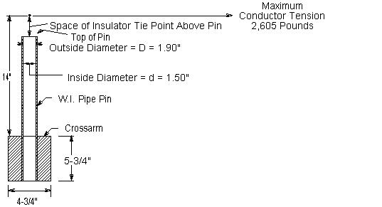
Bending moment (at crossarm) M = 2,605 x 14 = 36,470 pound–inches
![]()
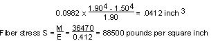
Assuming that the ultimate fiber stress of wrought iron is 48,000 pounds
per square inch, a single pin is not sufficient, as it provides a safety factor
of 0.542, ![]() for an assumed tension of 2,605 pounds in the conductor at maximum loading.
Since a safety factor of unity (Rule 47.5
) is required, two pins are necessary and therefore double crossarms, pins
and insulators are used on the poles supporting the crossing span.
for an assumed tension of 2,605 pounds in the conductor at maximum loading.
Since a safety factor of unity (Rule 47.5
) is required, two pins are necessary and therefore double crossarms, pins
and insulators are used on the poles supporting the crossing span.
Locust pins are to be used in this case for the private telephone conductors.
Although a 1–1/2 inch locust pin would be sufficient to withstand the conductor
tension of 570 pounds with a safety factor of at least unity, as required
by Rule 47.4
, care would be necessary to provide sufficient strength in the conductor
fastenings. In this problem, the private telephone conductors are considered
to be dead–ended at the ends of the crossing span.
8. Crossarms–Horizontal Loads
Power Circuits
The point of maximum bending moment will be at the crossarm through bolt
attaching the arm to the pole, at which point the cross section of the arm
is reduced by the amount of the bolt hole. Crossarms supporting the 60 kV
wires are to be Douglas fir, dense, dimensions 4–3/4” x 5–3/4” x 12’, bored
as illustrated below.
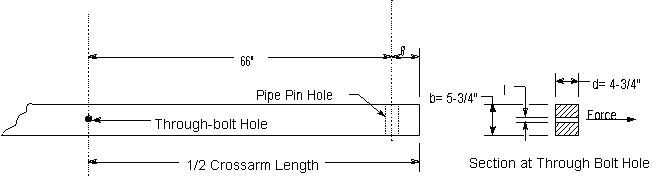
The section through the arm and the method of computing the fiber stress
is shown below.
Long–time loading: Since longitudinal conductor loads are normally balanced,
long–time horizontal loading of the power circuit crossarms need not be considered.
Single arm, Maximum loading, 25°F and an 8 lb wind
Bending moment = 2,605 x 66 = 171,930 pound–inches
![]()
b = 5.75” – 0.69 = 5.06”
d = 4.75”
s = 11/16” = 0.69”
![]()
Fiber Stress = Bending moment divided by
![]()
As the allowable value for modulus of rupture in bending under maximum loading
conditions is 6,300 lbs per sq. in. (see Table
5
, Rule 48.1
), a single crossarm of the size chosen provides a safety factor of only
0.70 for the assumed load at maximum loading conditions, whereas the provisions
of Rule 47.5
require a safety factor of unity. Double arms will, therefore, be used
in this problem to meet the strength requirements applicable to crossarms
at end supports of crossings. Double crossarm construction of this type with
separation maintained by space bolts is assumed to have a horizontal strength
equivalent to 130% of the sum of the strengths of two single crossarms acting
independently.
Maximum loading, 25°F and an 8 lb wind
Bending moment = 2,605 x 66 = 171,930 pound–inches
Single arm section modulus (same as previously calculated) = 19.0 inches
Double arm section modulus = 19.0 x 2 x 1.3 = 49.4 inches
![]()
As the allowable modulus of rupture for short–time loading is 6,300 lbs
per sq. in. then the double crossarms under these conditions will provide
a safety factor of 1.91, which meets the unity safety factor required by
Rule 47.5
.
Private Communication Circuit
At the crossing span, double crossarms are used on account of dead–end construction
due to change of conductor size. Current practice provides for this method
of construction although a singlearm has sufficient strength as is found form
the following calculations of modulus of rupture under the two limiting conditions
of loading:
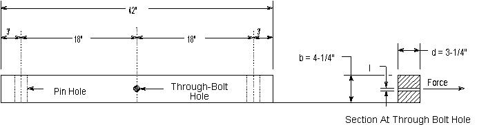
Long–time loading, 60°F and no wind
Bending moment = 448 x 18 = 8,064 pound–inches
![]()
where d = 3.25”
s = 0.69”
b = 4.25” – 0.69” = 3.56”
![]()
The allowable value for modulus of rupture in bending is 0.55 x 6,300 =
4,465 pounds per square inch and therefore with a single arm the factor of
safety under conditions of long–time loading is 2.69.
Maximum Loading
Bending moment = 570 x 18 = 10,260 pound–inches
Section modulus = 6.26 inches3 (as per calculations
above)
![]()
The allowable value for modulus of rupture in bending, under maximum loading
conditions, is 6,300 pounds per sq. in., therefore a single arm provides a
safety factor of 3.84 under these maximum loading conditions.
9. Crossarms - Vertical Loads
The vertical load on crossarms, where supports are approximately at the
same elevation, is due to the vertical load of conductors in each adjacent
span plus 200 pounds at the outer pin position. In the problem under consideration,
the conductor supports on the crossing poles (C and D) are at the same elevation,
and the supports at the adjacent poles (B and E) are 4.5 feet lower in elevation,
which difference in elevation is greater than the normal sag. Then the conductor
loading on a crossing span support would be one–half the weight of the conductor
of the crossing span plus one–half the conductor weight of a hypothetical
span, the curve of which passes through the points of support.
Half the length of the hypothetical span may be calculated as follows:
![]()
Where
X = 1/2 the hypothetical span in feet.
D = horizontal distance between supports in feet.
h = difference in elevation of supports in feet.
T = conductor tension in pounds.
w = weight of conductor in pounds per foot.
The total crossing support–load is calculated as follows:
![]()
The bending moment is: 334 x 66 = 22,040 pound–inches
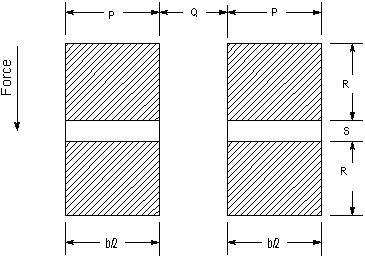
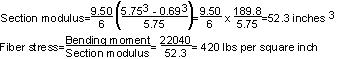
The method of calculating the unit fiber stress of the double crossarms
acting as a simple beam is as follows:
![]()
b = P + P = 9.50”
d = R + S + R = 5.75”
d1 = S = 0.69”
Long–Time Loading
As the allowable modulus of rupture in bending is 0.55 x 6,300 lbs per sq.
in. or 3,465 lbs per sq. in. (see Table 5
), the double crossarms of the size chosen provide a safety factor of 8.2.
The fiber stress in the double crossarms of the private telephone circuit,
similarly calculated, is found to be 196 lbs per sq. in. These arms obviously
meet the strength requirements for vertical loads on crossarms.
Shear, compression and torsion stresses are not considered in this problem
as they are negligible and likewise the effect of reduction of cross section
due to bolt holes is not considered except for the through bolt holes.
10. Poles
The crossing poles are western red cedar and their dimensions are as follows:
|
Length |
55 feet |
|
Height above ground |
48 feet |
|
Circumference at top |
28 inches |
|
Diameter at top |
8.9 inches |
|
Circumference at ground line |
49.0 inches |
|
Diameter at ground line |
15.6 inches |
Distance from ground line to conductors supported is given as follows:
|
Top supply conductors |
48’ 9” |
|
Middle supply conductors |
43’ 3” |
|
Lower supply conductors |
37’ 9” |
|
Private telephone conductors |
28’ 4” |
Ground level at base of pole is considered to be at the same elevation as
top of rail.
Dimensions of adjacent poles B and E are:
|
Length |
50 feet |
|
Height above ground |
43.5 feet |
|
Circumference of top |
28 .0 inches |
|
Diameter of top |
8.9 inches |
|
Circumference at ground line |
47.0 inches |
|
Diameter at ground line |
15.0 inches |
11. Transverse Load on Crossing Poles C and D
The moment at the ground due to an 8 pound wind pressure on conductors is:
![]()
Where:
|
L |
= |
Height of conductors above ground in feet |
|
n | = |
Number of wires |
|
S1 and S2 |
= |
Length of crossing and adjacent spans, respectively |
|
Ph |
= |
Horizontal load per lineal foot due to an 8 pound wind pressure on |
|
|
|
projected area of wire |
|
Ph |
= |
0.276 pounds per lineal foot for 00 AWG bare, stranded copper |
|
|
= |
0.108 pounds per lineal foot for 6 AWG bare, solid copper |
|
|
= |
0.085 pounds per lineal foot for 8 AWG bare, solid copper |
|
Mc0 |
= |
Moment due to pressure on top supply conductors |
|
Mc1 |
= |
Moment due to pressure on middle supply conductors |
|
Mc2 |
= |
Moment due to pressure on lower supply conductors |
|
Mc3 |
= |
Moment due to pressure on telephone conductors |
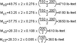
Total Moment due to Wind pressure on conductors =
13,510 lb-feet
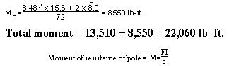
The moment at the ground due to an 8 pound wind pressure on the pole is:
![]()
Where:
|
Mp |
= |
Moment due to wind pressure on pole |
|
P |
= |
Pressure in lbs per sq. ft. on projected area of pole (8 lbs/sq. ft.) |
|
H |
= |
Height of pole above ground in feet (48’) |
|
D1 |
= |
Diameter of pole at ground in inches (15.6”) |
|
D2 |
= |
Diameter of pole at top in inches (8.9”) |
Where:
The allowable fiber stress for western red cedar poles to provide a factor
of safety of 4 is 1,500 pounds per sq. in., hence the crossing poles are not
required to be side guyed since they have a factor of safety of 8.5 for transverse
load.
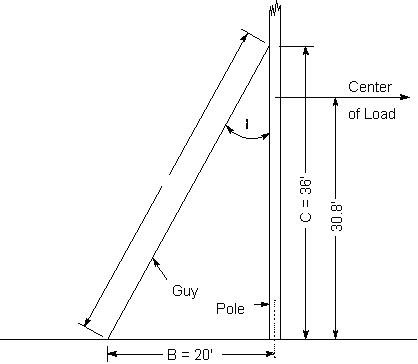
12. Side Guying
If side guying were required for the crossing poles C and D the method of
computing the same would be as follows:
Side guys are designed to take the entire transverse load of the pole, the
pole acting merely as a strut.
The transverse force acting on the poles will be due to wind pressure on
poles C and D and the transverse wind pressure on the conductors supported.
The length of conductor used in computing this transverse force will be equal
to one–half the distance between the guyed poles C and D, plus one–half the
length of the span adjacent to these poles.
The total wind pressure is computed as follows:
On Conductors
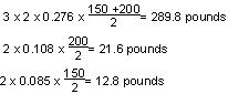
On Pole
![]()
Total Wind Pressure = 716.4 pounds
The total moment on the poles is the same as developed for “Transverse
load on poles” which was 22,060 pound–feet.
![]()
A side guy could not be attached at this center of load and provide the required
clearances from the communication line; therefore, for construction purposes
the guy is assumed attached just below the lowest supply crossarm at a distance
of 36 feet above ground.0
|
Let |
Mt |
= |
Total moment on pole = 22,060 pound–feet |
|
|
C |
= |
Height of guy attachment above ground = 36 feet (assumed) |
|
|
B |
= |
Distance of guy anchor from base of pole = 20 feet |
|
|
T |
= |
Tension in guy wire in pounds |
|
|
A |
= |
Length of guy = |
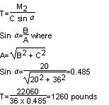
The specified safety factor for guys (Table
4
, Rule 44.1
) is 2 and, therefore, a guy having an ultimate strength of not less than
2,520 pounds is required. One 1/4 inch Siemens–Martin or a 5/16 inch common
galvanized–steel strand would meet the requirements for transverse load.
13. Longitudinal Load on Crossing Poles C and D
Rule 47.5
provides that crossing structures shall withstand at all times with
a safety factor of unity the unbalanced stress due to the combined pull toward
the crossing of one–third of the total number of conductors supported, the
pull in each such conductor being taken as the tension due to the specified
loading.
![]()
Location of conductors resulting in maximum load - two on top arm and one
on next arm below
Bending moment:
2 x 2,605 x 48.75 = 254,000 pound–feet
1 x 2,605 x 43.25 = 112,600 pound–feet
Total Moment = 366,600 pound–feet
![]()
The allowable value of modulus of rupture under this load is 6,000 lbs per
square inch, hence poles C and D must be head guyed for longitudinal load.
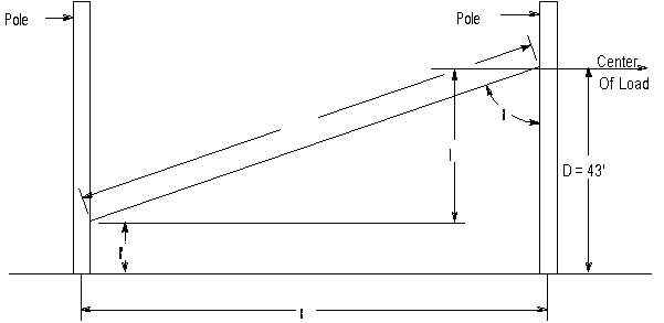
The head guy should be attached approximately at the normal center of load,
therefore:
The bending moment under full longitudinal load would be:
|
48.75 x 2 x 2,605 |
= |
254,000 pound–feet |
|
43.25 x 2 x 2,605 |
= |
225,300 pound–feet |
|
37.75 x 2 x 2,605 |
= |
196,700 pound–feet |
|
28.33 x 2 x 570 |
= |
32,300 pound–feet |
|
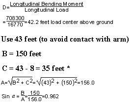
Total moment |
= |
708,300 pound–feet |
The total longitudinal load would be:
|
3(2 x 2,605) |
= |
15,630 pounds |
|
2 x 570 |
= |
1,140 pounds |
|
Total wire tensions |
= |
16,770 pounds |
Therefore, the center of longitudinal load is:
* Lower end of guy assumed 8 feet above ground on Poles A and E.
A guy attached at a point 43 feet above ground on pole C or D and at a point
8 feet above ground on pole B or E, respectively, would be required to withstand
a load of:
![]()
In this case, a 9/16 inch common, 7/16 inch Siemens–Martin, or 3/8 inch
high–strength guy strand would meet the requirements of Rule 47.5. The horizontal
load transmitted to pole B or E by such a head guy would be:
8,860 x sin đ = 8,860 x 0.962 = 8,520 pounds
The longitudinal moment on pole B and E would be:
8,520 x 8 = 68,160 pound–feet
and the fiber stress developed in pole B or E by the tension of 9,070 pounds
in the head guy would be:
![]()
Poles B and E would, therefore, be adequate to hold the contemplated guy
tension with a safety factor of unity as required by
Rule 47.5.