General Order 64
Appendix D
Method of Determining the Construction Requirements for a typical Crossing of “Class H” Supply Lines Over an Important Railroad and Signal Lines to Comply with the Requirements of These Rules for Light Loading Conditions.
The purpose of this appendix is to provide an example of a typical crossing of supply lines over railroads and signal lines to determine the various clearances and construction requirements necessary to comply with the rules. The actual construction of the crossing is made to conform to current good practice and indicated where and in what manner the minimum requirements of the rules are exceeded or maintained. The crossing diagram and dimensions are shown on the following page after this appendix. The primary data chosen for the crossing follow:
DATA OF CROSSING.
Number
of Circuits, Voltage and Phase.
Two
3-phase 60,000-volt circuits. One
private telephone circuit.
Configuration.
Power conductors of each circuit in
vertical plane on opposite ends of the crossarms. Private telephone circuit in horizontal plane.
Conductors.
Power circuits-6 No. 00 A.W.G. copper,
medium hard drawn, stranded, bare.
*Private
telephone circuit-2 No. 8 A.W.G.
copper, medium hard drawn, solid, bare.
*It is
assumed that the private signal circuit on the power line pole is run, operated
and maintained consistently, as a signal circuit as defined in Rule 17 (d), and for this reason change in conductor size at the crossing is
required.
Insulators.
Pin Type porcelain, to meet the requirements
of Rules 64 and 126 (d) 3, and 4.
Ties
and Conductor Fastenings.
To
meet the requirements of Rule 62(a).
Pins.
Iron pipe (extra strong) 1 ˝’’ (nominal) X
20 ˝’’ for power conductors – pins of each circuit metallically bonded together
to conform to the requirements of Rule 126 (d) 2. 1 ˝’’ X 9’’ locust pins for conductors of private telephone
circuit.
Crossarms.
Douglas fir 5 ľ’’ X 5 ľ’’ X 12’-0’’, 1.9’’ pin
holes –11/16’’ hole for pole bolt.
(Telephone circuit crossarm 3 Ľ’’ X 4 ˝’’.)
Crossarm
Braces.
To conform to Rule 62(a).
Poles.
Western red – cedar National Electric
Light Association specifications.
Pole
Framing.
As per dimensional
diagram.
Location
of Poles.
As per dimensional
diagram.
Length
of Crossing Span.
200 feet
Length
of Adjacent Spans.
150 feet
CONSTRUCTION REQUIREMTNS.
1. Conductor Sags (Normal Conditions, 60°F., no wind).
The
required sags of power and telephone conductors are determined from the minimum
sags curves of Appendix C.
For No. 00
A.W.G. copper, medium hard drawn, stranded, bar – Span 200 feet, Curve Sheet,
curve
2, gives the sag as 12.0 inches.
For No. 8
A.W.G. copper, medium hard drawn, solid, bar – Span 200 feet, Curve Sheet, curve
2, gives the sag as 13.2 inches.
In the
spans adjacent to the crossing span the supports are at different levels, and the
“apparent sags” are required. These are
equal to the normal sags for spans of the same length between supports at the
same level. Thus from, the curve
2 of
Appendix C, the apparent sags are 7.2 inches for the No. 8 A.W.G.
wire and 6.9 inches for the No. 00 A.W.G. wire.
2. Conductor Sags (Light Loading 25° F., 8 pounds wind)
Since no ice loading is considered, the vertical sags under the light loading condition will be less than normal sags at 60°F. and no wind. Consequently the clearances provided under light loading will be greater than normal conditions, and it is therefore only necessary to determine the elevations of supports to provide the required clearances under normal conditions, 60°F. and no wind. The tensions in the conductors loaded are found from Tables 13 and 14, Appendix B, to be as follows:
|
Copper Conductors |
150-foot span |
200-foot span |
|
No 00 A.W.G. medium hard drawn, stranded bare |
2,610 lbs. |
2,610 lbs |
|
No 8 A.W.G. medium hard drawn, solid bare |
324 lbs. |
324 lbs. |
3.
Conductor Separations at Supports.
Table 1,
case 6, column F, gives the minimum clearance of the conductors from the center
of the pole for supply conductors of this class as 18 inches. For circuits of the character under
consideration, where vertical configuration is employed, current good practice
employs a spacing of 5’6’’ from the center of the pole, which is greatly in
excess of the minimum required.
For a
private telephone circuit, Table 1, case 6, column B, provides a minimum
clearance for conductors of 15 inches from the center of the pole. Eighteen (18) inches is employed in this
case.
4.
Crossarm Spacing.
Table 2,
case 11, column H, gives the minimum vertical separation between wires on
different crossarms on the same poles for 60,000 volt circuits as 4 feet. Note (r) modifies this to allow a conductor
spacing equivalent to the table values for pin spacing of wires of the circuit
voltage which is (by Table 2, case 7, Column H) 36 inches. In the case under discussion the vertical
separation between crossarms has been taken as 5’6’’, conforming to current
good practice.
The minimum
separation between the lowest crossarm supporting power conductors and the
crossarm supporting a private telephone circuit is given by Table 2, case 11,
column C, as 6 feet. Current good
practice usually employs an 8-foot separation and it is so taken in this case.
5.
Clearances of Conductors Over Crossarms.
Table 1,
case 9, column F, gives the minimum clearance of conductors in the 60,000-volt
class above the supporting crossarms as 9 inches. Since in this case a 20 ˝’’ pin is employed, the clearance of the
conductor above the crossarm is 15 inches, which is in excess of the minimum
requirements.
Table 1,
case 9, column E, gives the minimum clearance of the private telephone
conductors above the supporting crossarm as 3 inches. This is adhered to in the case discussed.
6.
Vertical Clearance of Conductors Over
Highway, Pole lines and Railroad Tracks.
The poles
supporting the crossing span are 55 feet in length set 7 feet in the
ground. From the dimensions of the pole
framing diagram, the distance from the conductors of the private telephone
circuit to the ground is 28’6’’. The
ground level is given as the same elevation the as top of the rail.
The sag of
the signal conductors in the crossing span is given above as 13.2 inches. The plan gives the distances from supporting
pole C to the various structures crossed over as follows:
Telephone pole line – 37’6’’
Highway (center) – 60’0’’
Telegraph pole line on R.R r/w – 97’6’’
Center railroad tracks – 138’9’’
Railroad signal pole line – 180’0’’
Total length of crossing span, 200 feet.
Considering as an example the clearance of the private telephone circuit conductors above the crossed over telephone pole lead.
This point of crossing is from the nearest crossing pole C 37’6’’ or 18.75 percent of the crossing span length. The sag at 18.75 percent of the crossing span length is (from curve 12, Appendix C) 61 percent of the center sag. The center sag is 13.2’’, making the sag at the point of crossing 13.2’’ X 0.6’ =8.0’’. Therefore the clearance of private telephone conductors over the top of rail at the point of crossing with the telephone pole line is 28’6’’ - 8.0’’ = 27’10’’. As the top wire of the telephone pole line at this point is given as 24’, the clearance at this point from the private telephone circuit conductors will be 3’10’’, which is in excess of the minimum required clearance of 2’ given by Table 2, case 2, column c.
In a like manner the clearances of the private telephone circuit conductors at the other points of crossing are as follows:
|
Points of Crossing |
Clearance |
Minimum by rules |
|
Highway (center) |
27’7’’ |
18’0’’ |
|
Telegraph pole line |
3’5’’ |
2’0’’ |
|
Railroad tracks (center) |
27’7’’ |
25’0’’ |
|
Railroad signal pole line |
6’1.3’’ |
2’0’’ |
The clearances of the lower power conductors at the various points of crossing can likewise be computed and are as follows:
|
Points of Crossing |
Clearance |
Minimum by rules |
|
Telephone pole line |
13’0’’ |
8’0’’ |
|
Highway (center) |
36’9’’ |
30’0’’ |
|
Telegraph pole line |
12’7’’ |
8’0’’ |
|
Railroad tracks (center) |
36’9’’ |
34’0’’ |
|
Railroad signal pole line |
15’3’’ |
8’0’’ |
7.
Insulators.
In addition
to the electrical requirements set forth in Rules 64 and 126 (d) 3, and 4, the
insulators supporting the supply conductors shall have a safety factor
(mechanical) of over 3 the stresses they will be required to withstand for the
most severe condition of loading applying.
(Rule 52 (c).)
8. Pins, Ties and Conductor Fastenings.
Pins, ties
and conductor fastenings used in connection with pin type insulators shall have
sufficient strength to withstand a tension in the conductor of 700 pounds per
pin or fastening as a minimum (Rule 62 (a)).
When greater strength is necessary they shall be designed to withstand
with a safety factor of 2 the tension in the conductor under the specified
loading condition. In the case under
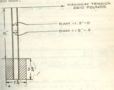
discussion wrought iron pipe pins are to be employed of the dimensions and
construction indicated below:
Bending moment (at crossarm) = M = 2,610 X 15=39,150 inch-pounds
Moment of
inertia ![]()
where ![]() and
and ![]()
Section
modulus ![]()
Fiber
stress ![]()
where c=D/2
Since the ultimate fiber stress for wrought iron is 45,000 pounds per square inc, a single pin is of this type is insufficient. Four such pins are required to provide a factor of safety of 2 and, as the unbalanced stress may be distruted over one or more poles adjacent to the crossing, double pins are required at poles B, C, D and E.
Conductor fastenings or ties are required to provide a safety factor of (2).
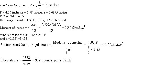
Locust pins 1 ˝’’ X 9’’ are employed for supporting the private telephone conductors. Since locust pins of these dimensions provide strength up to 1000 pounds tension in the conductor, with the conductor 3 ˝ inches above the crossarm (Rule 62 (a)) and the maximum tension in the conductor is only 324 pounds, the required factor of safety (2) is amply met.
9.
Crossarms.
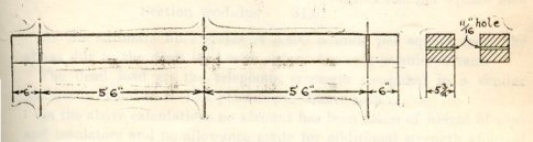
Crossarms
supporting the 60,000 volt wires are to be of Douglas fir, dimensions 5ľ’’ X 5
ľ’’ X 12’, bored as illustrated below:
Dead load on crossarms - The vertical load on the double crossarms (double arms are required on poles B, C, D and E by virtue of the double pin requirement) under maximum conditions of loading will be for each conductor equal to the weight per foot of wire (since no ice loading is considered) times one-half the sum of the length of the crossing and adjacent spans or
![]()
The weight per arm for conductors is 36 pounds.
Bending moment per arm
![]()
The point of maximum bending moment will be at the trough bolt attaching the arm to the pole, at which point the cross-section of the arm is reduced by the amount of the bolt hole.
The following shows the method of figuring the fiber stress at this point for one crossarm:
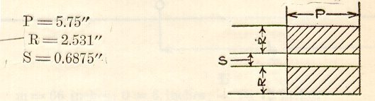
![]()
![]()
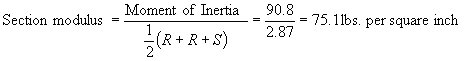
As the
ultimate fiber stress is 5,400 pounds per square inch, the stress due to the
dead load with safety factor 4 is unimportant.
The dead
load on the telephone crossarm computed in a similar manner is found to be 16.2
pounds per square inch.
In the
above calculations no account has been taken of weight of pins and insulators
and no allowance made for additional strength afforded by crossarm braces.
10. Unbalanced Wire Load on Crossarms.
It is
assumed that double crossarms (5ľ’’ X 5ľ’’ X 12’) will be employed space 8
inches apart, the separation being maintained by spreader blocks and
bolts. Crossarm construction of this
type is assumed to have 40 percent* of the
strength of two crossarms of the same dimensions connected as a rigid truss.
*When double crossarms are connected together
at the ends with spacing blocks, bolts or plates, their combined strength in
the direction of the pull of the conductors is in excess of double the strength
of a single crossarm and is less than the strength of two crossarms of similar
strength dimensions and spacing, connected as a rigid truss.
Allowance is made for this in the following manner:
(a) Double wood or steel crossarms, attached to poles, connected together at the ends by bolts with spacing nuts and washers or by bolts with pipe spacers of thirty (30) percent of the strength of two crossarms, of similar dimensions and spacing, connected as a rigid truss.
(b) Double wood or steel crossarms, , attached to poles, connected together at the ends by spacing blocks or plates, bolted or riveted to the crossarms will be considered as having a strength not in excess of forty (40) percent of the strength of the strength of two crossarms, of similar dimensions and spacing, connected as a rigid truss.
(c) Steel crossarms designed to take shear between the main members will be allowed a factor of strength in accordance with their construction.
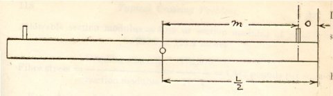
m = 66 inches; o = 6 inches; ![]()
Pull = 2,610 pounds on each pin
As it is necessary to consider the total load applied to one side only, the total bending moment is
2,610 X 66 =172,200 inch-pounds
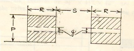
Section of Double Crossarms.
P=5.75’’ q (diameter of bolt hole) = ![]() R=5.75’’ S = 8’’
R=5.75’’ S = 8’’
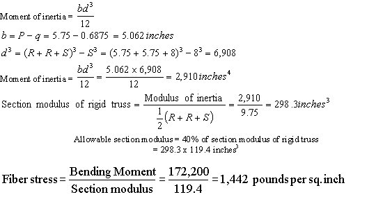
For a factor of safety of 4 required by the rules the allowable fiber stress is 1,350 pounds.
Thus double crossarms of this type upon the crossing poles C and D only would not be sufficient to meet the strength requirements. However, since, as previously discussed, double pins of the type employed herein are required at poles B, C, D and E, double crossarms are also required at the same poles and the strength requirements are therefore amply met.
Single crossarms, Douglas fir 3 Ľ’’ X 4 Ľ’’ X 42’’, are assumed for supporting the private telephone circuit at the crossing and the adjacent spans.
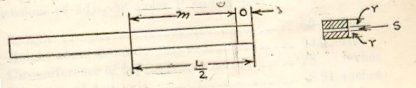
Since the allowable fiber stress for factor of safety 4 is 1,350 pounds the stress sue to the unbalanced load is well within the limit.
11. Poles
The crossing poles are Western red cedar and their dimensions, considering the clearances required, are as follows:
Length 55 feet
Height above ground 48 feet
Circumference at top 28 inches
Diameter at top 8.91 inches
Circumference 6 feet from butt 49 inches
Distance from ground line to conductors supported is given as follows:
Top supply conductors 48’7’’
Middle supply conductors 43’1’’
Lower supply conductors 37’7’’
Private telephone conductors 28’6’’
Ground level at base of pole is considered to be at the same elevation as top rail.
Dimensions of adjacent poles B and E are
Length 50 feet
Height above ground 43.5 feet
Circumference at top 28 inches
Diameter at top 8.91 inches
Circumference 6 feet from butt 47 inches
12. Transverse Load on Poles C and D
Due to 8-pound wind on projected areas of pole and conductors, maximum stress assumed at ground line.
The approximate moment at the ground, due to wind pressure on pole, is
![]()
where
P=Pressure
in pounds per square foot on projected area of pole
H=Height of
Pole above ground
D1=Diameter
of pole at ground in inches.
D2=Diameter
of pole at top in inches.
The moment
![]()
Where:
Ph = Horizontal load per lineal foot due to an 8 pound wind pressure on projected area of wire
L = Height of conductors above ground in feet
n = Number of wires
S1 and S2 = Length of crossing and adjacent spans, respectively
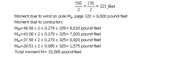
Mp = Moment due to wind pressure on pole
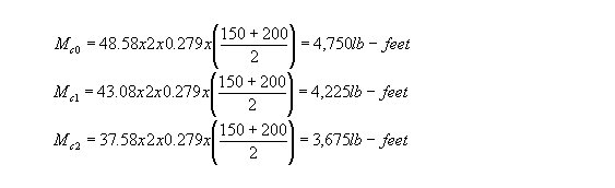
Mc0 = Moment due to pressure on top supply conductors
Mc1 = Moment due to pressure on middle supply conductors
Mc2 = Moment due to pressure on lower supply conductors
Mc3 = Moment due to pressure on telephone conductors
Total Moment =Mp + Mc0 + Mc1 + Mc2+ Mc3
![]()
Moment due to supply wires:
Ph = 0.279 pounds per linear foot for No. 00
A.W.G. copper, stranded, bare
Moment due to telephone conductors:
Ph = 0.085 pounds per linear foot for No. 8
A.W.G. copper, solid, bare
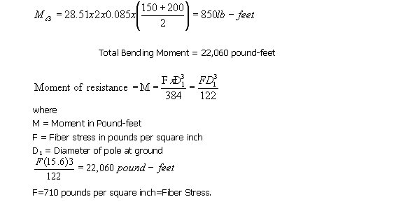
The allowable fiber stress for Western red cedar poles to provide a factor of safety of 4 is 1,275 pounds, hence the crossing poles do not require to be side guyed.
If poles of the minimum dimensions given in Rule 126(b) 3 were employed as is permissible, then
Length 55 feet
Height above ground 48 feet
Circumference at top 25.1 inches
Diameter at top 8 inches
Circumference 6 feet from butt 41 inches
Diameter 6 feet from butt 13.05 inches
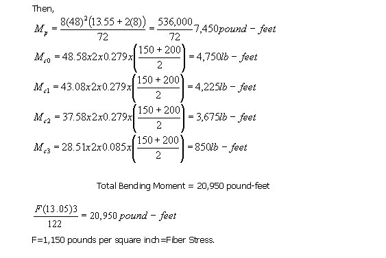
The minimum sized poles thus permitted will also meet the requirements for transverse load without the use of side guys.
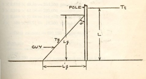
13. Side Guying
If side guying were required for poles C and D, and it was assumed physically impossible to side guy these poles, then poles B and E should be side guyed and the entire line between them must be Grade A, except as to transverse strength of poles, which shall not be dimensions smaller than set forth in Rule 126 (b) 3. The method of figuring side guys for poles B and E is as follows:
Side guys are figured to take the entire transverse load (between the guyed poles B and E), the pole acting simply as a strut.
The transverse force acting on the poles will be due to wind pressure on the pole and the transverse wind pressure on the conductors supported. The length of conductor used in figuring this transverse force will be equal to one-half the distance between the guyed poles B and E, plus one-half the length of the span adjacent to these poles, or to
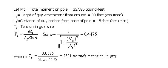
The specified factor of safety for guys is 3, hence a guy having an ultimate strength of not less than 7,503 pounds should be employed which can be obtained by using one Siemens-Martin 7/16- inch guy its equivalent having an ultimate strength of 9,000 pounds.
14. Unbalanced Load on Crossing Poles “C” and “D”.
(Rule 126 (b) 2) “To withstand at all times without failure, the unbalanced stress due to the combined pull toward the crossing of all the conductors supported, the pull in each conductor being taken as the tension due to the specified loading…”
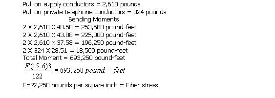
The allowable fiber stress under this unbalanced load is 5,100 pounds per square inch, hence poles C and D must be head guyed.
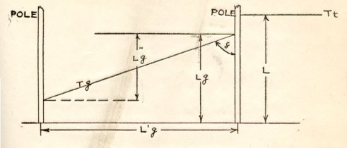
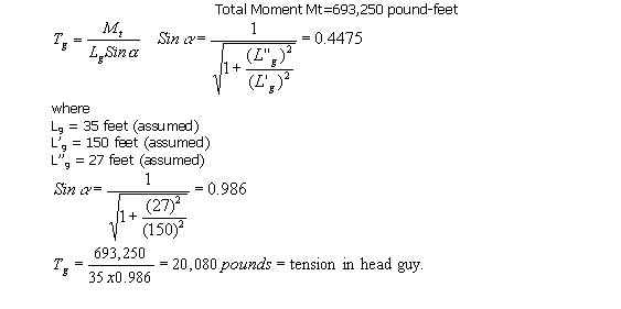
Under an unbalanced longitudinal stress as above considered, the pole, or, in this case the guy can be figured to withstand this unbalanced stress “without failure”; that is the guys can be figured, therefore, guys with ultimate strength of 20,080 pounds. There can be used, therefore, three 3/8 inch Siemens-Martin steel strands or equivalent having an ultimate strength of 11,000 pounds each. The unbalanced stress may be assumed to be distributed over one or more poles adjacent to the crossing poles. If so assumed one head guy may be installed on each of the crossing poles C and D and also on each of the adjoining poles B and E, each of these guys to be ˝-inch Siemens-Martin galvanized steel strand or equivalent having an ultimate strength of 11,000 pounds.