Original Version
Rule 54.9
54.9 Low Voltage Racks
A. General
Conductors of 0-750 volts may be attached to poles by means
of vertical racks of insulators or individual supports in vertical rack configuration.
Such construction is hereinafter termed "rack construction." Where rack construction
is employed, the following rules shall apply.
Note:
For Low Voltage Extended Rack Construction (Conductors
15 Inches Or More From Centerline Of Pole, But Not Less Than 3 Inches From
The Surface Of Pole) See Rule 54.12.
B. Pole Arrangement And Clearance
(1) Clearance From Poles: Conductors of 0-750 volts in rack construction may have clearances less than 15 inches from centerline and 3 inches from surface of pole, as specified in Table 1, Column D, Cases 8 and 9, respectively, but shall have a clearance of not less than 2 1/2 inches from the surface of pole (for interpretation of this 2 1/2-inch clearance see App. G, Fig. 60).
(2)
Conductor Arrangement: Not more than
7 conductors of not more than 2 circuits shall be attached to any pole in
a continuous rack group. In a rack group the conductors shall be of one ownership
and the vertical separations between line conductor attachments shall be
uniform.
Conductors, both line and service drop, in
rack configuration shall not be attached to more than 2 sides (there being
4 sides) of any pole at the level of anyone rack group. Climbing space in
conjunction with these attachments shall be maintained as specified in Rule
54.9-F.
C.
Conductor Material
All conductors of a rack group in the
same vertical plane shall be of the same material.
(1)
Urban Districts: Conductors
in rack construction in urban districts shall have a covering not less than
the equivalent of double braid weather-resistant covering.
(2)
Rural Districts:
Line conductors in rack construction in rural districts may be bare conductors
provided the vertical separation between conductors is not less than 12 inches
and conforms to the requirements of Rule 54.9-D where greater separation
is specified.
Note:
Resolution No. E-949 effective
February 11, 1957 authorized that the provisions of Rule 54.9-C1, 54.9-C2
and 54.9-D shall not be held to apply to the use of 0-750 volt duplex service
drop cable consisting of one suitably insulated conductor with a bare neutral
conductor as the line conductor between a pole supporting street light circuits
and metal and/or concrete electroliers or wood or steel poles where the latter
supports street light fixtures.
D.
Conductor Spacing
And Span Length
The vertical separation between conductors supported as a group in rack construction shall be not less than the following for span lengths as indicated:
| Minimum Vertical Length of Span (feet) |
Separation (inches) |
| 150 or less |
6 |
| 200 or less, but more than 150 |
8 |
| 330 or less, but more than 200 |
12 |
| More than 330 |
16 |
E.
Vertical
Clearance Between Conductor Levels
A vertical
clearance of not less than 6 feet shall be maintained between the top conductor
supported in rack construction at one level and conductors supported on the
same pole at the next level above except as provided in Rule 54.4-C6 for
lead wires and as modified below:
(1)
With Guard Arm Below Conductors of 750-22,500 Volts: The vertical clearance
between the top conductor in a rack group and conductors of 750-22,500 volts
at the next conductor level above, may be less than 6 feet but shall be not
less than 4 feet. If a clearance of less than 6 feet is used, all of the
following requirements shall be met:
A wood guard arm not less than 48 inches long shall be installed directly
above and approximately parallel to the top line conductor of such a rack
group; or where the conductor of a rack group dead-ends, the guard arm may
be placed above the rack at a right angle to the line conductor, provided
that no service drop conductor attached to a rack so guarded makes a horizontal
angle greater than 90 degrees with the vertical plane of the line conductors;
Conductors in such a rack group, which are so guarded shall not be ~ attached
to more than one side (there being four sides) of any pole; and
No service drop conductors supported on a rack with the guard arm installed
directly above and approximately parallel to the top line conductor of a
rack group shall pass between the surface of pole and the vertical plane
of the line conductors.
Any service drop conductors attached to and supported by the line conductors
shall have a clearance of not less than 15 inches from surface of pole (see
App. G, Fig. 43).
Each guard arm and its pole attachments are required by Rule 46 to withstand
a vertical load of 200 pounds at either end.
(2)
With Guard Ann Below Conductors of 0-750 Volts: The vertical clearance
between the top conductor in a rack group and conductors of 0-750 volts at
the next conductor level above may be less than 6 feet but shall be not less
than 4 feet. If a clearance of less than 6 feet is used, a wood guard arm
not less than 48 inches long shall be installed directly above and parallel
to the top line conductor of such a rack group.
(3)
Under a transformer: No guard arm will be required over line or service
drop conductors attached in rack construction to the surface of a pole directly
below a transformer installation provided that at that level all attachments
to the pole shall be approximately in the vertical plane through the center
lines of pole and transformer installation and no conductor so attached makes
an angle greater than 60 degrees with that plane. The top conductor so supported
shall have a vertical clearance of not less than 48 inches below the level
of conductors on the hanger arm; a vertical clearance not less than as specified
in Rule 54.4-C6 below the lowest point of the drip loop of primary leads
to the transformer; and a vertical clearance of not less than 10 inches below
the lowest part of the transformer case or hangers (see App. G, Fig. 33).
(4)
In Rural Districts: In rural districts (see definition, Rule 21.0-B)
where one circuit only of 7,500-22,500 volts is supported on the poles above
conductors in rack construction, the vertical clearance between the top conductor
in rack construction and the nearest 7,500-22,500 volt conductor level may
be less than 6 feet but not less than 4 feet and no guard arm is required.
(5)
Related Rack and Crossarm: Where conductors supported in rack construction
are connected to conductors supported on a crossarm on the same pole, the
vertical clearance between the level of conductors of 0-750 volts on the
crossarm and the nearest conductor in rack construction shall be not less
than 2 feet and climbing space shall be maintained in the same quadrant or
on the same side of pole through both conductor levels in accordance with
climbing space requirements in Rules 54.7 and 54.9-F. This provision is not
applicable where the crossarm is a combination arm.
F. Climbing Space In Rack Construction (see App. G, Fig. 32)
A climbing space shall be maintained through the levels of conductors supported
in rack construction and for a vertical distance of not less than 4 feet
above the top conductor and not less than 4 feet below the bottom conductor
so supported.
The width of the climbing space measured horizontally through the centerline
of pole shall be not less than 5 inches plus the diameter of the pole and
the extremities of such width shall be equidistant from the centerline of
pole. The depth of the climbing space shall be not less than 30 inches measured
perpendicularly to this climbing space boundary through the centerline of
pole. The width of the climbing space, perpendicular to and at the extremity
of this 30- inch depth dimension, shall be not less than 38 inches and neither
of the other two side boundaries shall make an angle of less than 90 degrees
with the boundary through the centerline of pole (see App. G, Fig. 32).
The position of the climbing space through the levels of conductors in rack
construction shall be related to climbing spaces through the levels of conductors
on crossarms in accordance with the requirements of Rule 54.7-A. The climbing
spaces through the levels of conductors of two or more rack groups which
are separated less than 6 feet shall be maintained in the same quadrant or
on the same side of pole.
Guys, vertical conductors attached to the surfaces of poles, and terminals,
which are listed in Rule 54.7-A4 as allowable climbing space obstructions,
are not permitted in climbing spaces through conductors in rack construction.
Strikeout and Underline Version
Rule 54.9
54.9
Low Voltage Racks
A.
General
Conductors of 0-750 volts may be attached to poles by means of vertical racks
of insulators or individual supports in vertical rack configuration. Such
construction is hereinafter termed "rack construction." Where rack construction
is employed, the following rules shall apply.
Note:
For Low Voltage Extended Rack Construction (Conductors 15 Inches Or
More From Centerline Of Pole, But Not Less Than 3 Inches From The Surface
Of Pole) See Rule 54.12.
B.
Pole Arrangement And Clearance
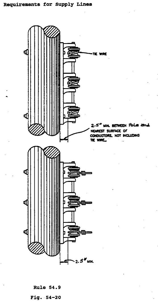
(1)
Clearance From Poles: Conductors of 0-750 volts in rack construction
may have clearances less than 15 inches from centerline and 3 inches from
surface of pole, as specified in Table 1, Column D, Cases 8 and 9, respectively,
but shall have a clearance of not less than 2 1/2 2.5 inches from the surface
of pole (for interpretation of this 2 1/2-2.5
inch clearance see App. G, Fig.
60 Figure 54-20).
(2)
Conductor Arrangement: Not more than 7 conductors of not more than
2 circuits shall be attached to any pole in a continuous rack group. In a
rack group the conductors shall be of one ownership and the vertical separations
between line conductor attachments shall be uniform.
Conductors, both line and service drop, in rack configuration shall not be
attached to more than 2 3 sides (there being 4 sides) of any pole at the
level of anyone rack group. Climbing space in conjunction with these attachments
shall be maintained as specified in Rule 54.9-F.
C.
Conductor Material
All conductors of a rack group in the same vertical plane shall be of the
same material.
(1)
Urban Districts: Conductors in rack construction in urban districts
shall have a covering not less than the equivalent of double braid weather-resistant
covering.
(2)
Rural Districts: Line conductors in rack construction in rural districts
may be bare conductors provided the vertical separation between conductors
is not less than 12 inches and conforms to the requirements of Rule 54.9-D
where greater separation is specified.
Note:
Resolution No. E-949 effective February 11, 1957 authorized that the
provisions of Rule 54.9-C1, 54.9-C2 and 54.9-D shall not be held to apply
to the use of 0-750 volt duplex service drop cable consisting of one suitably
insulated conductor with a bare neutral conductor as the line conductor between
a pole supporting street light circuits and metal and/or concrete electroliers
or wood or steel poles where the latter supports street light fixtures.
D.
Conductor Spacing And Span Length
The vertical separation between conductors supported as a group in rack construction shall be not less than the following for span lengths as indicated:
| Minimum Vertical Length of Span (feet) |
Separation (inches) |
| 150 or less |
6 |
| 200 or less, but more than 150 |
8 |
| 330 or less, but more than 200 |
12 |
| More than 330 |
16 |
E.
Vertical Clearance Between Conductor Levels
A vertical clearance of not less than 6 feet shall be maintained between
the top conductor supported in rack construction at one level and conductors
supported on the same pole at the next level above except as provided in
Rule 54.4-C6 for lead wires and as modified below:
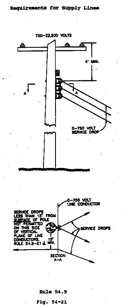
(1) With Guard Arm Below Conductors of 750-22,500 Volts: The vertical clearance
between the top conductor in a rack group and conductors of 750-22,500 volts
at the next conductor level above, may be less than 6 feet but shall be not
less than 4 feet. If a clearance of less than 6 feet is used, all of the
following requirements shall be met:
A wood guard arm not less than 48 inches long shall be installed directly
above and approximately parallel to the top line conductor of such a rack
group; or where the conductor of a rack group dead-ends, the guard arm may
be placed above the rack at a right angle to the line conductor, provided
that no service drop conductor attached to a rack so guarded makes a horizontal
angle greater than 90 degrees with the vertical plane of the line conductors;
Conductors in such a rack group, which are so guarded shall not be ~ attached
to more than one side (there being four sides) of any pole; and
No service drop conductors supported on a rack with the guard arm installed
directly above and approximately parallel to the top line conductor of a
rack group shall pass between the surface of pole and the vertical plane
of the line conductors.
Any service drop conductors attached to and supported by the line conductors
shall have a clearance of not less than 15 inches from surface of pole (see
App. G, Fig. 43).
Each guard arm and its pole attachments are required by Rule 46 to withstand
a vertical load of 200 pounds at either end.
a)
In tangent construction a guard arm shall be installed directly above
and approximately parallel to the top line conductor of such a rack group.
Service drop conductors supported on a rack with the guard arm installed
directly above and approximately parallel to the top line conductor of a
rack group shall not pass between the surface of pole and the vertical plane
of the line conductors.
b) In deadend construction, the guard arm shall be placed above the rack
at a right angle to line conductor, provided that no service drop attached
to a rack so guarded makes a horizontal angle greater than 90 degrees with
the vertical plane of line conductors.
c) Conductors in such a rack group, which are so guarded shall not be attached
to more than one side of any pole.
d) Any service drop conductors attached to and supported by the line conductors shall have a clearance of not less than 15 inches from surface of pole (See figure 54-21)
(2)
With Guard Arm Below Conductors of 0-750 Volts: The vertical clearance
between the top conductor in a rack group and conductors of 0-750 volts at
the next conductor level above may be less than 6 feet but shall be not less
than 4 feet. If a clearance of less than 6 feet is used, a wood guard arm
not less than 48 inches long shall be installed directly above and parallel
to the top line conductor of such a rack group.
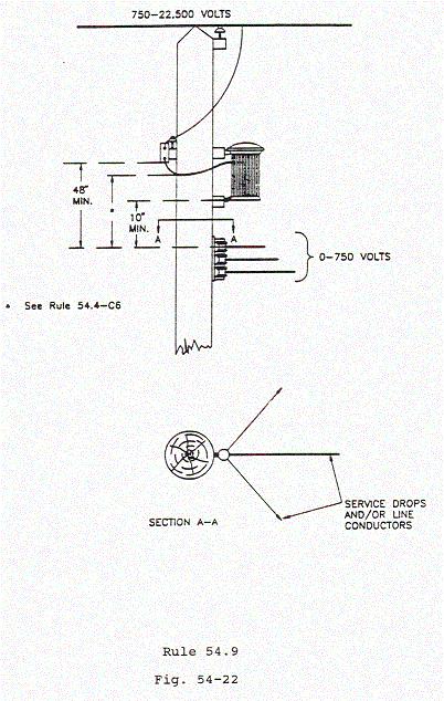
(3)
Conductors Deadended Under a Equipment transformer: No guard arm will
be required over line or service drop conductors attached in rack configuration
construction deadended to on the surface of a pole directly below equipment
(e.g., transformer, capacitor and other similar apparatus). Such conductors
shall have a vertical clearance of not less than: a transformer installation
provided that at that level all attachments to the pole shall be approximately
in the vertical plane through the center lines of pole and transformer installation
and no conductor so attached makes an angle greater than 60 degrees with
that plane. The top conductor so supported shall have a vertical clearance
of not less than 48 inches below the level of conductors on the hanger arm;
a vertical clearance not less than as specified in Rule 54.4-C6 below the
lowest point of the drip loop of primary leads to the transformer; and a
vertical clearance of not less than 10 inches below the lowest part of the
transformer case or hangers (see App. G, Fig. 33).
a) 4 feet below unprotected conductors: and
b) As specified in Rule 54.4-C6 below the lowest point of drip loop of the primary leads to the transormer(s): and
c) 10 inches below the lowest part of the equipment case(s)
or hangers(s)
(See Figure 54-22)
(4)
In Rural Districts: In rural districts (see definition, Rule 21.0-B)
where one circuit only of 7,500-22,500 volts is supported on the poles above
conductors in rack construction, the vertical clearance between the top conductor
in rack construction and the nearest 7,500-22,500 volt conductor level may
be less than 6 feet but not less than 4 feet and no guard arm is required.
(5 3)
Related Rack and Crossarm: Where conductors supported in rack construction
are connected to conductors supported on a crossarm or extended rack on the
same pole, the vertical clearance between the level of conductors of 0-750
volts on the crossarm or extended rack and the nearest conductor in rack
construction shall be not
not be less than 2 feet and climbing space shall be maintained
in the same quadrant or on the same side of pole through both conductor levels
in accordance with climbing space requirements in Rules 54.7 and 54.9-F.
This provision is not applicable where the crossarm is a combination arm.
(4) Multiconductor Cable with a bare neutral: Multiconductor cable with a bare neutral. 0 � 750volts (Rule 54.10), may be installed with a minimum vertical separation above or below conductors in rack configuration of 10 inches for spans not to exceed 200 feet and 12 inches for spans in excess of 200 feet.
EXCEPTION: When rack construction is present, the most stringent climbing space requirements of Rule 54.9-F shall be maintained through both levels.
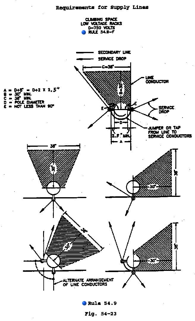
F.
Climbing Space In Rack Construction (see App. G, Fig. 32 Figure 54-23)
A c Climbing space shall be maintained through the levels of conductors supported
in rack construction, and for a vertical distance of not less than 4 feet
above the top conductor and not less than 4 feet below the bottom conductor
so supported. Where conductors in rack construction are installed at
a pole top, the climbing space shall extend up to the level of the lowest
conductor of the rack group, and need not be provided through and above such
levels.
The width of the climbing space measured horizontally through the centerline of
the pole shall be not be less than 5 inches plus the diameter of the pole
and the extremities of such width shall be equidistant from the centerline
of pole. The depth of the climbing space shall be not be less than 30 inches
measured perpendicularly to this climbing space boundary through the centerline
of pole. The width of the climbing space, perpendicular to and at the extremity
of this 30- inch depth dimension, shall be not be less than 38 inches and
neither of the other two side boundaries shall make an angle of less than
90 degrees with the boundary through the centerline of pole (see App. G,
Fig. 32). (See Figure 54-23).
The position of the climbing space through the levels of conductors in rack construction shall be related to climbing spaces through the levels of conductors on crossarms in accordance with the requirements of Rule 54.7-A, Extended rack Rule 54.12-F and Multiconductor Cable with Bare Neutral Rule 54.10-F. The climbing spaces through the levels of conductors of two or more rack groups which are separated less than 6 feet shall be maintained in the same quadrant or on the same side of pole.
Guys, vertical conductors attached to the surfaces of poles, and terminals,
which are listed in Rule 54.7-A4 as allowable climbing space obstructions,
are not permitted in climbing spaces through conductors in rack construction.
Final Version
Rule 54.9
54.9 Low Voltage Racks
A. General
Conductors of 0-750 volts may be attached to poles by means of vertical racks of insulators or individual supports in vertical rack configuration. Such construction is hereinafter termed "rack construction." Where rack construction is employed, the following rules shall apply.
Note: For Low Voltage Extended Rack Construction (Conductors 15 Inches Or More From Centerline Of Pole, But Not Less Than 3 Inches From The Surface Of Pole) See Rule 54.12.
B. Pole Arrangement And Clearance
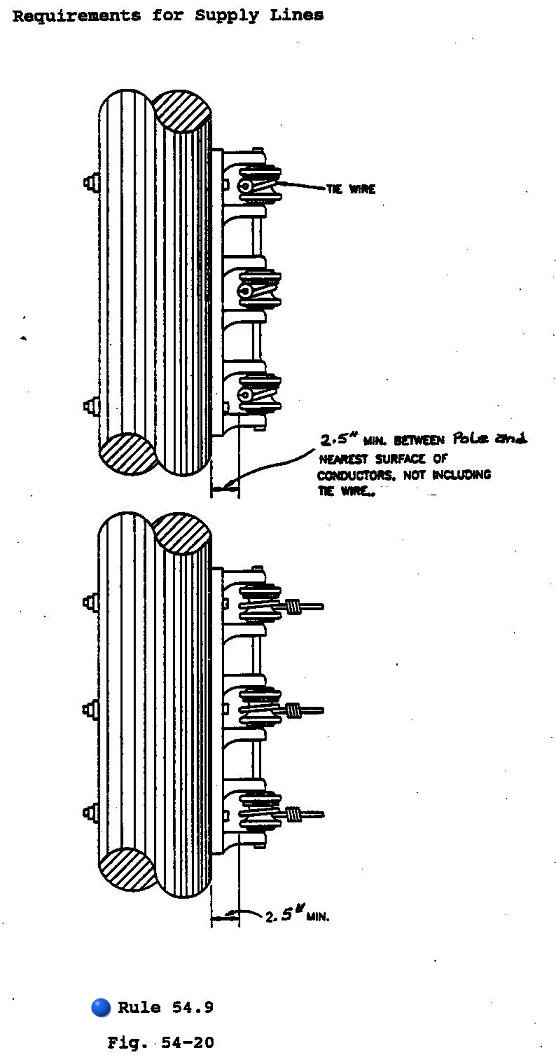
(1) Clearance From Poles: Conductors of 0-750 volts in rack construction may have clearances less than 15 inches from centerline and 3 inches from surface of pole, as specified in Table 1, Column D, Cases 8 and 9, respectively, but shall have a clearance of not less than 2.5 inches from the surface of pole (for interpretation of this 2.5 inch clearance see Figure 54-20).
(2)
Conductor Arrangement: Not more than 7 conductors of not more than 2
circuits shall be attached to any pole in a continuous rack group. In a rack
group the conductors shall be of one ownership and the vertical separations
between line conductor attachments shall be uniform.
Conductors, both line and service drop, in rack configuration shall not be
attached to more than 3 sides of any pole at the level of anyone rack group.
Climbing space in conjunction with these attachments shall be maintained
as specified in Rule 54.9-F.
C.
Conductor Material
All conductors of a rack group in the same vertical plane shall be of the
same material.
(1) Urban Districts: Conductors in rack construction in urban districts shall have a covering not less than the equivalent of double braid weather-resistant covering.
(2) Rural Districts: Line conductors in rack construction in rural districts may be bare conductors provided the vertical separation between conductors is not less than 12 inches and conforms to the requirements of Rule 54.9-D where greater separation is specified.
D. Conductor Spacing And Span Length
The vertical separation between conductors supported as a group in rack construction
shall be not less than the following for span lengths as indicated:
| Minimum Vertical Length of Span (feet) |
Separation (inches) |
| 150 or less |
6 |
| 200 or less, but more than 150 |
8 |
| 330 or less, but more than 200 |
12 |
| More than 330 |
16 |
E. Vertical Clearance Between Conductor Levels
A vertical clearance of not less than 6 feet shall be maintained between
the top conductor supported in rack construction at one level and conductors
supported on the same pole at the next level above except as provided in
Rule 54.4-C6 for lead wires and as modified below:
(1)
With Guard Arm Below Conductors of 750-22,500 Volts: The vertical clearance
between the top conductor in a rack group and conductors of 750-22,500 volts
at the next conductor level above, may be less than 6 feet but shall be not
less than 4 feet. If a clearance of less than 6 feet is used, all of the
following requirements shall be met:
a) In tangent construction a guard arm shall be installed directly above
and approximately parallel to the top line conductor of such a rack group.
Service drop conductors supported on a rack with the guard arm installed
directly above and approximately parallel to the top line conductor of a
rack group shall not pass between the surface of pole and the vertical plane
of the line conductors.
b) In deadend construction, the guard arm shall be placed above the rack
at a right angle to line conductor, provided that no service drop attached
to a rack so guarded makes a horizontal angle greater than 90 degrees with
the vertical plane of line conductors.
c) Conductors in such a rack group, which are so guarded shall not be attached
to more than one side of any pole.
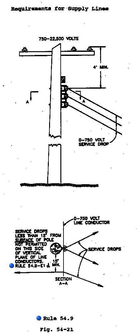
d) Any service drop conductors attached to and supported by the line conductors
shall have a clearance of not less than 15 inches from surface of pole (See
figure 54-21)
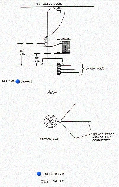
(2) Conductors Deadended Under a Equipment: No guard arm will be required over drop conductors in rack configuration deadended on the surface of a pole directly below equipment (e.g., transformer, capacitor and other similar apparatus). Such conductors shall have a vertical clearance of not less than
a) 4 feet below unprotected conductors: and
b) As specified in Rule 54.4-C6 below the lowest point of drip loop of the primary leads to the transormer(s): and
c) 10 inches below the lowest part of the equipment case(s) or hangers(s)
(See Figure 54-22)
(3) Related Rack and Crossarm: Where conductors supported in rack construction are connected to conductors supported on a crossarm or extended rack on the same pole, the vertical clearance between the level of conductors of 0-750 volts on the crossarm or extended rack and the nearest conductor in rack construction shall not be less than 2 feet and climbing space shall be maintained in the same quadrant or on the same side of pole through both conductor levels in accordance with climbing space requirements in Rules 54.7 and 54.9-F. This provision is not applicable where the crossarm is a combination arm.
(4) Multiconductor Cable with a bare neutral: Multiconductor cable with a bare neutral. 0 � 750volts (Rule 54.10), may be installed with a minimum vertical separation above or below conductors in rack configuration of 10 inches for spans not to exceed 200 feet and 12 inches for spans in excess of 200 feet.
EXCEPTION: When rack construction is present, 3the most stringent climbing
space requirements of Rule 54.9-F shall be maintained through both levels.
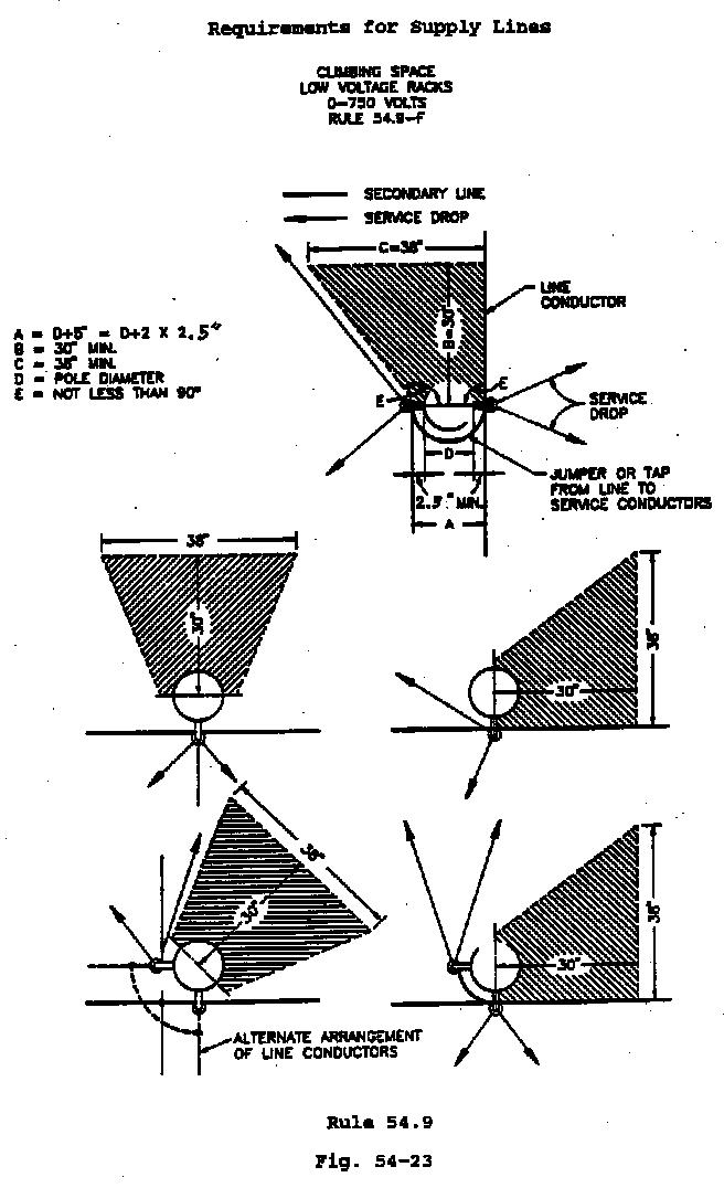
F. Climbing Space In Rack Construction (see Figure 54-23)
Climbing space shall be maintained through the levels of conductors supported
in rack construction, for a vertical distance of not less than 4 feet above
the top conductor and not less than 4 feet below the bottom conductor so
supported. Where conductors in rack construction are installed at a
pole top, the climbing space shall extend up to the level of the lowest conductor
of the rack group, and need not be provided through and above such levels.
The width of the climbing space measured horizontally through the centerline
of the pole shall not be less than 5 inches plus the diameter of the pole
and the extremities of such width shall be equidistant from the centerline
of pole. The depth of the climbing space shall not be less than 30 inches
measured perpendicularly to this climbing space boundary through the centerline
of pole. The width of the climbing space, perpendicular to and at the extremity
of this 30- inch depth dimension, shall not be less than 38 inches and neither
of the other two side boundaries shall make an angle of less than 90 degrees
with the boundary through the centerline of pole (See Figure 54-23).
The position of the climbing space through the levels of conductors in rack
construction shall be related to climbing spaces through the levels of conductors
on crossarms in accordance with the requirements of Rule 54.7-A, Extended
rack Rule 54.12-F and Multiconductor Cable with Bare Neutral Rule 54.10-F.
The climbing spaces through the levels of conductors of two or more rack
groups which are separated less than 6 feet shall be maintained in the same
quadrant or on the same side of pole.
Guys, vertical conductors attached to the surfaces of poles, and terminals,
are not permitted in climbing spaces through conductors in rack construction.