Original Version
Rule 54.12
54.12 New Rule
Strikeout and Underline Version
Rule 54.12
54.12 Low Voltage Extended Racks, 0 - 750 Volts (Conductors 15 inches or More from Centerline of Pole, But Not Less than 3 inches from the Surface of Pole)
A. General
Conductors of 0 - 750 volts may be attached to poles by means of vertical racks of insulators or individual extended supports in vertical rack configuration. Such construction is hereinafter termed “extended rack construction”. Where extended rack construction is employed, the following rules shall apply.
Note: For Low Voltage Rack Construction (Conductors Less than 15 Inches from Centerline Of Pole, But Not Less than 2–1/2 inches from The Surface Of Pole) See Rule 54.9 .
B. Pole Arrangement and Clearance
(1) Clearance from Poles: Conductors in extended rack construction shall have minimum clearances of 15 inches from center line of pole and 3 inches from the surface of pole as specified in Table 1, Column D, Cases 8 and 9 , respectively.
(2) Conductor Arrangement: Where conductors, both line and service drop, are supported by extended racks, such extended racks may be attached to three sides of a pole (there being 4 sides) at the levels of any extended rack group. Climbing space in conjunction with such attachments shall be maintained as specified in Rule 54.12–F .
C. Conductor Material
All conductors of a rack group in the same vertical plane shall be of the same material.
D. Conductor Spacing and Spreader Brackets
(1) Vertical Separation: The vertical separation between conductors,supported as a group in extended rack construction, shall not be less than 8 inches, such separation to be maintained in a span by suitably insulating spreader brackets attached to such line conductors within the span.
(2) Spreader Brackets: Spreaders shall be used at points in spans where one or more midspan service drops are attached to and supported by the line conductors. Also, spreaders shall be so spaced as to limit spans between spreaders or between spreaders and poles to not over 135 feet.
E. Vertical Clearance between Conductor Levels
A vertical clearance shall be maintained between the top conductor supported in the extended rack group at one level and conductors supported on the same pole at the next level above as provided in Table 2, Cases 9 to 13 and for lead wires Rule 54.4–C6 .
Related Extended Rack Construction and Other Types of Construction: Where conductors supported in extended rack construction are connected to conductors supported on other types of construction (crossarm etc.) climbing space shall be maintained in the same quadrant or on the same side of pole in accordance with climbing space requirements in Rules 54.7 , 54.9 , 54.10 or 54.12–F whichever is related to the climbing space selected.
F. Climbing Space in Extended Rack Construction
The climbing space in extended rack construction shall be maintained through the level of conductors supported in extended rack construction and for a vertical distance of not less than 4 feet above and below such conductors. The position of the climbing space through the level of conductors in extended rack construction shall be related to climbing space for conductor levels above and below such extended rack construction in accordance with Rules 54.7 , 54.10 , 54.11 and 93 . The depth of the climbing space shall be measured from the center line of the pole.
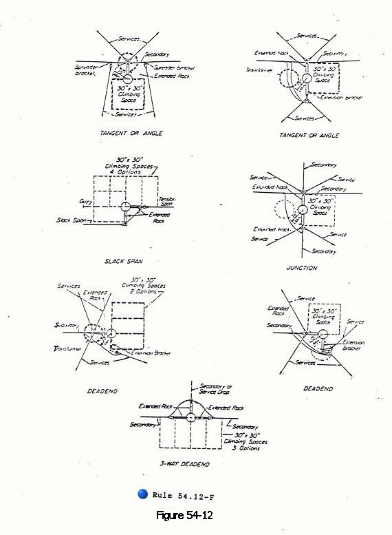
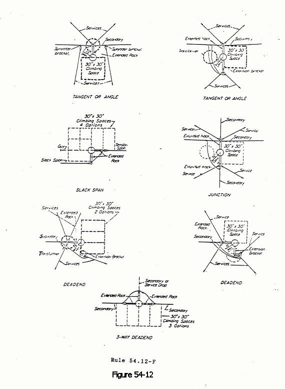
(1) Dimensions: The dimensions of the climbing space shall be 30 inches square, and shall be provided on one side of the pole with the extremities of such width equidistant from the centerline of pole. On poles on which transformers are pole–bolted in line with primary conductors, a 30 inch square climbing space shall be provided in one quadrant or one side of the pole (See Figure 54–12).
(2) With Conductors Deadended and on Corner Poles: On poles with the extended rack conductors dead–ended and on corner poles, a 30 inch climbing space shall be provided in one quadrant or on one side of the pole (see Figure 54–12).
(3) Allowable Climbing Space Obstructions: Suitably protected vertical runs or risers and ground wires attached to the surface of the poles, and guys, are allowed in climbing spaces provided that no more than two guys (provided they are separated at the pole by a vertical distance of not more than 18 inches) or one vertical riser, run, or ground wire is installed in any 4-foot vertical section of climbing space. The terminals or terminal fittings of risers or runs shall not be installed within climbing spaces.
Final Version
Rule 54.12
54.12 Low Voltage Extended Racks, 0 - 750 Volts (Conductors 15 inches or More from Centerline of Pole, But Not Less than 3 inches from the Surface of Pole)
A. General
Conductors of 0 - 750 volts may be attached to poles by means of vertical racks of insulators or individual extended supports in vertical rack configuration. Such construction is hereinafter termed “extended rack construction”. Where extended rack construction is employed, the following rules shall apply.
Note: For Low Voltage Rack Construction (Conductors Less than 15 Inches from Centerline Of Pole, But Not Less than 2–1/2 inches from The Surface Of Pole) See Rule 54.9 .
B. Pole Arrangement and Clearance
(1) Clearance from Poles: Conductors in extended rack construction shall have minimum clearances of 15 inches from center line of pole and 3 inches from the surface of pole as specified in Table 1, Column D, Cases 8 and 9 , respectively.
(2) Conductor Arrangement: Where conductors, both line and service drop, are supported by extended racks, such extended racks may be attached to three sides of a pole (there being 4 sides) at the levels of any extended rack group. Climbing space in conjunction with such attachments shall be maintained as specified in Rule 54.12–F .
C. Conductor Material
All conductors of a rack group in the same vertical plane shall be of the same material.
D. Conductor Spacing and Spreader Brackets
(1) Vertical Separation: The vertical separation between conductors,supported as a group in extended rack construction, shall not be less than 8 inches, such separation to be maintained in a span by suitably insulating spreader brackets attached to such line conductors within the span.
(2) Spreader Brackets: Spreaders shall be used at points in spans where one or more midspan service drops are attached to and supported by the line conductors. Also, spreaders shall be so spaced as to limit spans between spreaders or between spreaders and poles to not over 135 feet.
E. Vertical Clearance between Conductor Levels
A vertical clearance shall be maintained between the top conductor supported in the extended rack group at one level and conductors supported on the same pole at the next level above as provided in Table 2, Cases 9 to 13 and for lead wires Rule 54.4–C6 .
Related Extended Rack Construction and Other Types of Construction: Where conductors supported in extended rack construction are connected to conductors supported on other types of construction (crossarm etc.) climbing space shall be maintained in the same quadrant or on the same side of pole in accordance with climbing space requirements in Rules 54.7 , 54.9 , 54.10 or 54.12–F whichever is related to the climbing space selected.
F. Climbing Space in Extended Rack Construction
The climbing space in extended rack construction shall be maintained through the level of conductors supported in extended rack construction and for a vertical distance of not less than 4 feet above and below such conductors. The position of the climbing space through the level of conductors in extended rack construction shall be related to climbing space for conductor levels above and below such extended rack construction in accordance with Rules 54.7 , 54.10 , 54.11 and 93 . The depth of the climbing space shall be measured from the center line of the pole.
(1) Dimensions: The dimensions of the climbing space shall be 30 inches square, and shall be provided on one side of the pole with the extremities of such width equidistant from the centerline of pole. On poles on which transformers are pole–bolted in line with primary conductors, a 30 inch square climbing space shall be provided in one quadrant or one side of the pole (See Figure 54–12).
(2) With Conductors Deadended and on Corner Poles: On poles with the extended rack conductors dead–ended and on corner poles, a 30 inch climbing space shall be provided in one quadrant or on one side of the pole (see Figure 54–12).
(3) Allowable Climbing Space Obstructions: Suitably protected vertical runs or risers and ground wires attached to the surface of the poles, and guys, are allowed in climbing spaces provided that no more than two guys (provided they are separated at the pole by a vertical distance of not more than 18 inches) or one vertical riser, run, or ground wire is installed in any 4-foot vertical section of climbing space. The terminals or terminal fittings of risers or runs shall not be installed within climbing spaces.