Original Version
Rule 54.7-A
54.7-A. Climbing Space
Climbing space, measured from centerline of pole, shall be provided on one side or in one quadrant of all poles or structures, with dimensions as specified in Rules 54.7-A1, 54.7-A2 and 54.7-A3. For climbing space dimensions where post insulators are utilized see Rule 54.11-F.
The climbing space shall be maintained in the same position for a distance of not less than 4 feet vertically both above and below each conductor level through which it passes. Compliance with this requirement necessitates that the position of the climbing space shall not be changed through conductor levels which are less than 4 feet apart. Where the vertical distance between consecutive conductor levels is 4 feet or more, and less than 8 feet the position of the climbing space through such consecutive levels may be shifted not more than one-quarter of the distance around the pole. Where a conductor is installed at the top of a pole under the provisions of Rule 54.4-D8, the climbing space shall extend up to the level of such pole-top conductor but need not be provided through and above such level.
Allowable obstruction of these climbing spaces, where necessary, are specified in Rule 54.7-A4
Bolts bonded to or used for the attachment of dead-end hardware of a circuit of any voltage in horizontal (wood crossarm) configuration may project into the climbing space provided they are covered with a suitable non-conducting material as specified in Rule 22.2-F. If such bolts are bonded, a positive electrical contact shall be made.
The covering of bolts, required by this rule , shall not apply to:
1) Bolts associated with circuits of 0 to 750 volts at any level on a pole or structure.
2) Bolts associated with circuits of more than 7,500 volts when located at the top level of a pole.
No part of any guy contacting or connected to a metal pin or part of dead-end hardware, shall be located in the climbing space.
(1) Dimensions Where Crossarms are Not Involved:
Climbing space through the
levels of conductors deadended on poles in vertical configuration shall be a
square of the horizontal dimensions tabulated below; and one side of such
climbing space shall be bounded by the vertical plane of the dead-ended
conductors with the centerline of pole bisecting such side (see App. G, Fig, 15)
Voltage of Conductors |
Dimensions of Square |
750-7500 volts |
30inches |
7500-46,000 volts |
36 inches |
More than 46,000 volts |
36 inches plus � inch Per kV in excess Of 46kV. |
For climbing space dimensions for low voltage rack construction see Rule 54.9-F
(2) Dimensions Where Line Arms Only Are Involved:
The climbing space through levels where line arms without related buck arms are present on poles or structures shall be on one side or face of the pole, with the center line of pole approximately midway on one side of the climbing space (see App. G Fig. 16), and shall have the following dimensions:
For conductors of 0-7500 volts, the climbing space shall be not less than 30 inches square except that for combination arm construction the climbing space shall be not less than 36 inches square. (see Rule 54.8-E for additional requirements where service drops from combination line arms are involved.)
For conductors of 750-46,000 volts the climbing space shall not be less than 36 inches square.
For conductors of more than 46,000 volts the climbing space shall be a square the sides of which shall be not less than 36 inches plus � inch per kV in excess of 46 kV.
The above dimensions may be reduced not more than 2 percent because of line angles.
The climbing space required by this rule may be shifted laterally not more than 5 inches under the condition that (a) the mid-point of the side of the climbing space coinciding with the center line of, the pole shall be not more than 5 inches from the center line of the pole, and (b) that full climbing space dimensions shall be maintained, but without the use of the 2% reduction where the shift is more than 2 inches.
(3)
Dimensions Where Buck Arms Are
Involved: The climbing space where line arms and related buck arms are involved
on pole or structures shall be in a quadrant and shall have at least the
dimensions, determined according to voltage classification as given below. These dimensions are based on the minimum
clearance from center line of pole (Table 1, Case
8) and minimum pin spacings (Table 2, Case 15) for the voltages involved, with the pin position numbered
outward from the pole on the climbing side.
Where metal back braces are used
they shall be considered as one of the arms of double arm construction.
a)
For Conductors of 0-750 Volts: Where
single line arm and buck arm construction is involved and the climbing space is
left open opposite the single arm, the No. 1 pin Position shall be left vacant
in the single arm. (See App G, Fig 18.)
Where double
line arm and double buck arm construction is involved, the No. 1 pin position
shall be left vacant in each arm. (see App. G, Fig.
19)
b)
For conductors of More than 750 Volts:
Where single arm and single buck arm construction is involved and the climbing
space is left open on the opposite side of the pole from the arms, the No. 1
pin position shall be left vacant in both line arm and buck arm (see App. G, Fig. 20). As an alternative, where the
conductors are of 750-7500 volts, the No. 1 and No. 2 pin positions in one arm
may be left vacant provided the arms involved are in top positions on the pole.
Where double line arm and single
buck arm, or vice versa, construction is involved and the climbing space is
left open on the side of the pole opposite the single arm, the No. 1 pin
position shall be left vacant in both line arm and buck arm (see App. G, Fig. 21). As an alternative, where the
conductors are of 750-7500 volts the No. 1 and No. 2 pin positions may be left
vacant in the single arm provided the arm involved are in top positions on the
pole.
Where double line arm and double
buck arm construction is involved the No. 1 pin position shall be left vacant
in one double arm and the No. 1 and No. 2 pin positions shall be left vacant in
the other double arm. (See
App. G, Fig 22.)
Where a single circuit of more
than 7,500 volts is in horizontal configuration at the top of the pole,
climbing space has to be provided only up to and not through the top level and
the No. 1 pin position need not be left vacant.
c) For Combination Arm Construction with Line Arm and
Line Buck Arm or Service Buck Arm: (See Rule 54.8-E for additional
requirements where service drops are involved.)
Where the vertical separation
between conductor levels on line and buck arms is not less than 4 feet and the
climbing space is in a 0-750 volt quadrant, the climbing space dimensions shall
be not less than those prescribed in Rule 54.7-A3a for 0-750 volt conductors
provided that the required vacant pin conductors provided that the required
vacant pin spaces shall be in addition to the 36-inch horizontal conductor
separation required in Rule 54.4-C2b.
(See App. G, Figs 23, 24 and 25.)
Where the vertical separation
between conductor levels on line and buck arms is not less than 4 feet and the
climbing space is in a 750-7500 volt conductors provided that the required
vacant volt conductors provided that the required vacant pin spaces shall be in
addition to the 36-inch horizontal conductor separation required in Rule 54.4-C2b. (See App. G, Figs 26, 27 and
28.)
Where the vertical separation
between conductor levels the vertical separation between conductor levels on
line and buck arms is less than 4 feet such separation shall not be less than 2
feet and the climbing space dimensions, in any quadrant, shall be not less than
those prescribed in Rule 54.7-A3b for 750-7500 volt conductors, provided that
the required vacant pin spaces shall be in addition to the 42-inch horizontal
conductor separation required in Rule 54.4-C2b. (See App. G Figs 29, 30 and 31.)
d) Alternatives: Where a single line arm or single buck
arm is involved and it is impractical to locate the climbing space in the
quadrant on the opposite side of the pole from the single arm, it may be
located in another quadrant provided that any single arm or arms within the
climbing space shall be treated as a double arm.
In applying the pin position
spacings as prescribed in Rule 54.7 not less than the minimum spacings of Table
2, Case 15 shall be used. In the event
the crossarms used are not bored for the minimum spacings, a spacing of
conductors to give equivalent dimensions will be considered as meeting the
requirements.
(4)
Allowable Climbing Space Obstructions: Crossarms and
their supporting members are allowed in climbing spaces provided that, where
buck arms are involved, any arms within climbing spaces are treated as double
arms.
Suitably protected vertical
conductors attached tot eh surfaces of poles, and guys, (except those guys
contacting metal pins or dead-end hardware as specified in Rule 52.7-D) are
allowed in climbing spaces provided that not more than two
guys (provided they are separated at the pole by a vertical distance of not
more than 18 inches) and one vertical
riser, run, or ground wire are installed in any 4-foot vertical section of
climbing space.
Pin-type insulators which support line conductors of 20,000 volts or less
may extend not more than one-half of their diameter into the climbing space.
Dead-end or strain type insulators which support line conductors of 0-750
volts may extend not more than one-half of their diameter into the climbing
space.
Space bolts used for the attachment of dead-end hardware of a circuit of
any voltage located below a circuit at the top of the pole may project into
the climbing space provided they are protected with a suitable insulating
cover, having an insulating value equal to the insulators on the associated
circuit, and further that the area of the climbing space on a horizontal
plane is not reduced by more than 10%.
Modifications of these
requirements for rack construction are specified in Rule 54.9-F.
Strikeout and Underline Version
Rule 54.7-A
54.7-A. Climbing Space
Climbing space shall be
maintained from the ground level. measured from centerline of pole,
shall be provided on one side or in one quadrant of all poles or structures,
with dimensions as specified in Rules 54.7-A1, 54.7-A2 and 54.7-A3. For climbing space dimensions where post
insulators are utilized see Rule 54.11-F.
The climbing space shall be maintained in the same position for a
distance of not less than 4 feet vertically both above and below each conductor
level through which it passes. To comply Compliance with this
requirement necessitates that the position of the climbing space shall
not be changed through conductor levels which are less than 4 feet apart. Where the vertical distance between
consecutive conductor levels is 4 feet or more, and less than 8 feet the
position of the climbing space through such consecutive levels may be shifted
not more than one-quarter (90 degrees) of the distance around the pole.
Where a single level of circuitry is installed at the top of a pole, the climbing space shall extend up to the level. Where a conductor is installed at the top of a pole under the provisions of Rule 54.4-D8, the climbing space shall extend up to the level of such pole-top conductor but need not be provided through and above such level.
This rule is not applicable to non-climbable poles. See Rule 22.0-D for definition.
Climbing space measured from center line of pole shall be provided on one side or in one quadrant of all poles or structures with dimensions as specified in the following:
|
|
Rules |
Wood Crossarm Construction |
54.7-A 1 & 2 |
Without Wood Crossarms (More than 750 Volts) |
54-11-F |
Low Voltage Rack Construction |
54.9-F |
Low Voltage Multiconductor Cable w/Bare Neutral |
54.10-F |
Poles Jointly Used |
84.7 & 93 |
Allowable Obstructions of These Climbing Spaces |
54.7-A 3 54.9-F 54.11-G 84.7-E |
Allowable obstruction of these
climbing spaces, where necessary, are specified in Rule 54.7-A4
Bolts bonded to or used for
the attachment of dead-end hardware of a circuit of any voltage in horizontal
(wood crossarm) configuration may project into the climbing space provided they
are covered with a suitable non-conducting material as specified in Rule
22.2-F. If such bolts are bonded, a
positive electrical contact shall be made.
The
covering of bolts, required by this rule , shall not apply to:
1) Bolts associated with
circuits of 0 to 750 volts at any level on a pole or structure.
2) Bolts associated with
circuits of more than 7,500 volts when located at the top level of a pole.
No part of any guy
contacting or connected to a metal pin or part of dead-end hardware, shall be
located in the climbing space.
The climbing space required by this rule may be shifted laterally not more than 5 inches on the condition that the midpoint of the side of the climbing space coinciding with the center line of the pole shall not be more than 5 inches, from the center line of the pole.
The dimensions specified in the above rules may be reduced not more than 2% because of line angles and minor field variations.
(1)
Dimensions Where Crossarms are Not
Involved:
Climbing space through the
levels of conductors deadended on poles in vertical configuration shall be a
square of the horizontal dimensions tabulated below; and one side of such
climbing space shall be bounded by the vertical plane of the dead-ended
conductors with the centerline of pole bisecting such side (see App. G, Fig,
15)
|
|
|
|
|
|
|
|
For climbing space dimensions
for low voltage rack construction see Rule 54.9-F.
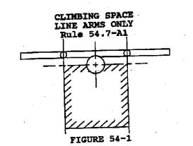
(2)
Dimensions Where Line Arms Only Are Involved:
The climbing space through levels
where line arms without related buck arms are present on poles or structures
shall be on one side or face of the pole, with the center line of pole
approximately midway on one side of the climbing space (see App. G Fig. 16
Figure 54-1), and shall have the following dimensions:
For conductors of 0-7500 volts, the climbing space shall be not less than 30 inches square except that for combination arm construction the climbing space shall be not less than 36 inches square. (see Rule 54.8-E for additional requirements where service drops from combination line arms are involved.)
For conductors of 750-46,000
volts the climbing space shall not be less than 36 inches square.
For conductors of more than
46,000 volts the climbing space shall be a square the sides of which shall be
not less than 36 inches plus � inch per kV in excess of 46 kV.
The above dimensions may be
reduced not more than 2 percent because of line angles.
The climbing space required by
this rule may be shifted laterally not more than 5 inches under the condition
that (a) the mid-point of the side of the climbing space coinciding with the
center line of, the pole shall be not more than 5 inches from the center line
of the pole, and (b) that full climbing space dimensions shall be maintained,
but without the use of the 2% reduction where the shift is more than 2 inches.
Voltage of Conductors |
Dimensions of Square |
750-7500 volts |
30inches |
7500-46,000 volts |
36 inches |
More than 46,000 volts |
36 inches plus � inch Per kV in excess Of 46kV. |
(23)
Dimensions Where Buck Arms Are Involved:
The climbing space where line arms and related buck arms are involved on pole
or structures shall be in a quadrant as defined below: and shall have
at least the dimensions, determined according to voltage classification as
given below. These dimensions are based
on the minimum clearance from center line of pole (Table 1, Case 8) and minimum
pin spacings (Table 2, Case 15) for the voltages involved, with the pin
position numbered outward from the pole on the climbing side.
Where metal back braces are
used they shall be considered as one of the arms of double arm construction.
a)
For Conductors of 0-750 Volts: Where
single line arm and buck arm construction is involved and the climbing space is
left open opposite the single arm, the No. 1 pin Position shall be left vacant
in the single arm. (See App G, Fig 18.)
Where double line arm and
double buck arm construction is involved, the No. 1 pin position shall be left
vacant in each arm. (see App. G, Fig.
19)
b)
For conductors of More than 750 .Volts:
Where single arm and single buck arm construction is involved and the climbing
space is left open on the opposite side of the pole from the arms, the No. 1
pin position shall be left vacant in both line arm and buck arm (see App. G,
Fig. 20). As an alternative, where the
conductors are of 750-7500 volts, the No. 1 and No. 2 pin positions in one arm
may be left vacant provided the arms involved are in top positions on the pole.
Where double line arm and
single buck arm, or vice versa, construction is involved and the climbing space
is left open on the side of the pole opposite the single arm, the No. 1 pin
position shall be left vacant in both line arm and buck arm (see App. G, Fig.
21). As an alternative, where the
conductors are of 750-7500 volts the No. 1 and No. 2 pin positions may be left
vacant in the single arm provided the arm involved are in top positions on the
pole.
Where double line arm and
double buck arm construction is involved the No. 1 pin position shall be left
vacant in one double arm and the No. 1 and No. 2 pin positions shall be left
vacant in the other double arm. (See
App. G, Fig 22.)
Where a single circuit of
more than 7,500 volts is in horizontal configuration at the top of the pole,
climbing space has to be provided only up to and not through the top level and
the No. 1 pin position need not be left vacant.
a) Where the Vertical Clearance Between Conductors on Line and Buck Arms is Four Feet or More: The climbing space shall be provided on one side or face of the pole for each arm as specified in Rule 54.7-A1.
b) Where the Vertical Clearance Between Conductors on Line and Buck Arms is Less Than Four Feet: The climbing space shall be provided through such levels and located in a quadrant and shall have at least the following dimensions (See Figure 54-2.)
|
Voltage of Conductors |
Dimensions of Square |
0-7500 Volts |
30 inches |
7500-35000 Volts |
42 inches |
For circuitry located at pole top, the climbing space specified in Rule 54.7-A1 may be applied to the lower arm and up to but not through the conductors on the top arm (see Figure 54-3.).
c)
For Combination Arm Construction with
Line Arm and Line Buck Arm or Service Buck Arm: (See Rule 54.8-E for additional requirements where service drops
are involved.)
Where the vertical separation
between conductor levels on line and buck arms is not less than 4 feet and
the climbing space is in a 0-750 volt quadrant, the climbing space shall
be provided on one side or face of the pole for each level as specified in Rule
54.7-A1. dimensions shall be not less than those prescribed in Rule
54.7-A3a for 0-750 volt conductors provided that the required vacant pin
conductors provided that the required vacant pin spaces shall be in addition to
the 36-inch horizontal conductor separation required in Rule 54.4-C2b. (See App. G, Figs 23, 24 and 25.)Where the vertical separation
between conductor levels on line and buck arms is not less than 4 feet such
separation shall not be less than 2 feet, and the climbing space shall
not be less than prescribed in Rule 54.7-A2b and the dimensions shall be in
accordance with the highest voltage adjacent to the climbing quadrant (See
figure 54-4) is in a 750-7500 volt conductors provided that the required
vacant volt conductors provided that the required vacant pin spaces shall be in
addition to the 36-inch horizontal conductor separation required in Rule
54.4-C2b.. (See App. G, Figs 26, 27 and
28.)Where the vertical separation
between conductor levels the vertical separation between conductor levels on
line and buck arms is less than 4 feet such separation shall not be less than 2
feet and the climbing space dimensions, in any quadrant, shall be not less than
those prescribed in Rule 54.7-A3b for 750-7500 volt conductors, provided that
the required vacant pin spaces shall be in addition to the 42-inch horizontal
conductor separation required in Rule 54.4-C2b. (See App. G Figs 29, 30 and 31.)
d)
Alternatives: Where a single line arm or
single buck arm is involved and it is impractical to locate the climbing space
in the quadrant on the opposite side of the pole from the single arm, it may be
located in another quadrant provided that any single arm or arms within the
climbing space shall be treated as a double arm.
In applying the pin position
spacings as prescribed in Rule 54.7 not less than the minimum spacings of Table
2, Case 15 shall be used. In the event
the crossarms used are not bored for the minimum spacings, a spacing of
conductors to give equivalent dimensions will be considered as meeting the
requirements.
(34)
Allowable Climbing Space Obstructions:
Crossarms and their supporting
members are allowed in climbing spaces.
provided that, where buck arms are involved, any arms within climbing
spaces are treated as double arms. Insulators and their attaching brackets
which support line conductors may extend not more than one-half of their
diameter into the climbing space.
Suitably protected vertical
conductors attached to the surfaces of poles, and guys, (except those guys
contacting metal pins or dead-end hardware as specified in Rule 52.7-D) are
allowed in climbing spaces provided that not more than two guys (provided they
are separated at the pole by a vertical distance of not more than 18 inches)
and one vertical riser, run, or ground wire are installed in any 4-foot
vertical section of climbing space. The
terminals or terminal fittings of risers or runs shall not be installed within
climbing spaces.
Pin-type insulators which
support line conductors of 20,000 volts or less may extend not more than
one-half of their diameter into the climbing space. Dead-end or strain type insulators which support line conductors
of 0-750 volts may extend not more than one-half of their diameter into the
climbing space.
Space bolts bonded to
or used for the attachment of dead-end hardware of a circuit of any voltage
in horizontal (wood crossarm) configuration may project into the climbing
space provided they are covered with non-conducting material as specified in
Rule 22.2-F. If such bolts are bonded,
a positive electrical contact shall be made.l located below a circuit at the top of the pole may project
into the climbing space provided they are protected with a suitable insulating
cover, having an insulating value equal to the insulators on the associated
circuit, and further that the area of the climbing space on a horizontal plane
is not reduced by more than 10%.The covering of bolts required by this rule
shall not apply to:
a) Bolts associated with circuits of 0 to 750 volts at any level on pole or structure.
b) Bolts associated with circuits of more than 7500 volts when located at the top level of a pole.
Modifications of these requirements for rack construction are specified in Rule 54.9-F; for switches in Rule 58.5-D: and for climbing space without wood crossarms in Rule 54.11-G.
Final Version
Rule 54.7-A
54.7-A. Climbing Space
Climbing space shall be maintained from the ground level. The climbing space shall be maintained in the same position for a distance of not less than 4 feet vertically both above and below each conductor level through which it passes. To comply with this requirement the position of the climbing space shall not be changed through conductor levels which are less than 4 feet apart. Where the vertical distance between consecutive conductor levels is 4 feet or more, and less than 8 feet the position of the climbing space through such consecutive levels may be shifted not more than one-quarter (90 degrees) of the distance around the pole.
Where a single level of circuitry is installed at the top of a pole, the climbing space shall extend up to the level. Where a conductor is installed at the top of a pole under the provisions of Rule 54.4-D8, the climbing space shall extend up to the level of such pole-top conductor but need not be provided through and above such level.
This rule is not applicable to non-climbable poles. See Rule 22.0-D for definition.
Climbing space measured from center line of pole shall be provided on one side or in one quadrant of all poles or structures with dimensions as specified in the following:
|
|
Rules |
Wood Crossarm Construction |
|
Without Wood Crossarms (More than 750 Volts) |
|
Low Voltage Rack Construction |
|
Low Voltage Multiconductor Cable w/Bare Neutral |
|
Poles Jointly Used |
|
Allowable Obstructions of These Climbing Spaces |
The climbing space required by this rule may be shifted laterally not more than 5 inches on the condition that the midpoint of the side of the climbing space coinciding with the center line of the pole shall not be more than 5 inches, from the center line of the pole.
The dimensions specified in the above rules may be reduced not more than 2% because of line angles and minor field variations.
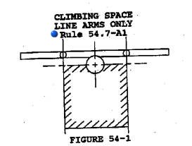
(1)
Dimensions
Where Line Arms Only Are Involved:
The climbing space through levels
where line arms without related buck arms are present on poles or structures
shall be on one side or face of the pole, with the center line of pole
approximately midway on one side of the climbing space (see Figure 54-1), and
shall have the following dimensions:
Voltage of Conductors |
Dimensions of Square |
750-7500 volts |
30inches |
7500-46,000 volts |
36 inches |
More than 46,000 volts |
36 inches plus � inch Per kV in excess Of 46kV. |
(2) Dimensions Where Buck Arms Are Involved: The climbing space where line arms and related buck arms are involved on pole or structures shall be in a quadrant as defined below:
a) Where the Vertical Clearance Between Conductors on Line and Buck Arms is Four Feet or More: The climbing space shall be provided on one side or face of the pole for each arm as specified in Rule 54.7-A1.
b) Where the Vertical Clearance Between Conductors on Line and Buck Arms is Less Than Four Feet: The climbing space shall be provided through such levels and located in a quadrant and shall have at least the following dimensions (See Figure 54-2.)
|
Voltage of Conductors |
Dimensions of Square |
0-7500 Volts |
30 inches |
7500-35000 Volts |
42 inches |
For circuitry located at pole top, the climbing space specified in Rule 54.7-A1 may be applied to the lower arm and up to but not through the conductors on the top arm (see Figure 54-3.).
c)
For Combination Arm Construction with
Line Arm and Line Buck Arm or Service Buck Arm: (See Rule 54.8-E for additional requirements where service drops
are involved.)
Where the vertical separation
between conductor levels on line and buck arms, the climbing space shall be
provided on one side or face of the pole for each level as specified in Rule
54.7
Where the vertical separation
between conductor levels on buck arms is not less than 4 feet such separation
shall not be less than 2 feet, and the climbing space shall not be less than
prescribed in Rule 54.7-A2b and the dimensions shall be in accordance with the
highest voltage adjacent to the climbing quadrant (See figure 54-4)
(3)
Allowable Climbing Space Obstructions:
Crossarms and their supporting
members are allowed in climbing spaces.
Insulators and their attaching brackets which support line conductors
may extend not more than one-half of their diameter into the climbing space.
Suitably protected vertical
conductors attached to the surfaces of poles, and guys, (except those guys
contacting metal pins or dead-end hardware as specified in Rule 52.7-D) are
allowed in climbing spaces provided that not more than two guys (provided they
are separated at the pole by a vertical distance of not more than 18 inches)
and one vertical riser, run, or ground wire are installed in any 4-foot
vertical section of climbing space.
Bolts bonded to or used for the
attachment of dead-end hardware of a circuit of any voltage in horizontal (wood
crossarm) configuration may project into the climbing space provided they are
covered with non-conducting material as specified in Rule 22.2-F. If such bolts are bonded, a positive
electrical contact shall be made.
The covering of bolts required by this rule
shall not apply to:
a) Bolts associated with circuits of 0 to 750 volts at any level on pole or structure.
b) Bolts associated with circuits of more than 7500 volts when located at the top level of a pole.
Modifications of these requirements for rack construction are specified in Rule 54.9-F; for switches in Rule 58.5-D: and for climbing space without wood crossarms in Rule 54.11-G.