Original Version
Rule 58.1
58.1 Enclosed Equipment (Transformers, Capacitors, Regulators, etc.)
A. Position on Pole
(1) Multiple Units: Where more than one unit is installed on a pole, they shall be placed on the same side of the pole.
(2) Pole Top Extensions: Equipment shall not be supported on pole top extensions.
EXCEPTION: Pole top extensions that conform with strength requirements for a whole pole (See Rule 49.1–A ) may be used to support equipment.
B.
Case and Lead Wire
Clearances (See Tables 58–1 & 58–2 )
(1)
Unprotected Lead Wire Clearances:
Unprotected vertical and lateral leads between line conductors and equipment
shall comply with Rules 54.6 and 54.4–C6 ; and with the clearances specified
in Table 1, Cases 8 and 9 ; and
Table 2, Cases 15, 16 and 17 .
Such lead wires may be installed in the working space but shall not be installed
in the climbing space.
The clearance specified in Table
1, Case 8, Columns D and E , need not apply to apparatus installed on poles
consisting of single–pole structures or on crossarms attached thereto, provided
that terminals and lead wires are not less than 6 inches from surface of pole
instead of 3 inches specified in Table 1, Case 9, Columns D and E , and have as much as
possible of the clearances specified in Table 1, Case 8, Columns D and E. No reduction of the
clearances specified in Table 1, Case
8, Columns D and E is permitted for interconnection wiring of polyphase
installations nor to any lead wire passing between pole and apparatus.
(2)
Cases above Ground: Cases of equipment supported on
poles or structures shall be not less than 17 feet above the ground except that
in areas which are not in any way accessible to vehicles, the clearance of cases
above ground may be less than 17 feet provided all cases which are less than 8
feet above ground shall be effectively grounded.
(3)
From Hardware: Equipment cases, hangers, and other
metal parts in contact therewith shall clear through bolts, arm braces of metal,
and other hardware elements, by not less than 1.5 inches; except that such cases
and hangers shall clear crossarm braces and crossarm through bolts by not less
than 1 inch air–gap distance and 1.5 inch creepage distance.
The minimum clearance of 1.5 inches need not apply to through bolts in
metallic contact with equipment cases or metal parts thereof nor to through
bolts supporting heel arms, provided the portion of such through bolts extending
into the climbing space is covered with non–conducting material as specified in
Rule 22.2 .
(4)
From Guys: Equipment cases and their hangers shall
not be less than 4 inches from all portions of guys which are 6 inches or more
from the surface of poles or crossarms at the guy attachments. Such cases and
hangers shall not be less than 1.5 inches from all portions of guys which are
within 6 inches of the surface of poles or crossarms at the guy
attachment.
C.
Equipment Cutouts or Other Equipment Disconnecting
Devices
Equipment cutouts, fuses, disconnects or switches shall be located
so that they are readily accessible from climbing and working spaces. Such
devices or their connecting leads shall not extend into the climbing space, but
may extend into the working space.
The vertical clearance between equipment cutouts, fuses, disconnects or
switches and unprotected conductors of other circuits below shall not be less
than the clearances required between conductors as specified in Table 2, Cases 8 to 13 .
The horizontal clearance between equipment cutouts, fuses, disconnects or
switches and unprotected conductors of different phase or polarity shall not be
less than the clearances specified in Table 2, Case 17 .
The provisions of this rule shall not apply to partial underground
distribution systems.
D.
Ungrounded Case Clearances from Line Conductors (See Table 58–2 )
E. Grounded Case Clearances from Line Conductors (See Rule 54.4–G )
F.
Bonding
Cases of equipment may be bonded together but shall not be bonded to
cutouts, metal pins or deadend
hardware.
|
Table 58–1 Unprotected Bus and Lead Wire Clearances |
|||
|
Case |
Nature of Clearance |
Clearances Required |
|
|
750 Volts - 22.5 kV |
22.5 kV & above |
||
|
Above Ground |
|
|
|
|
1 |
Single Pole Structure |
22.5 Feet |
27.0 Feet |
|
2 |
Two or More Pole Structure |
22.5 Feet (a) |
27.0 Feet (a) |
|
From Buildings - Horizontal |
|
|
|
|
3 |
With Windows, Fire Escapes, etc. |
6.0 Feet (b) |
6.0 Feet |
|
4 |
Without Windows, Fire Escapes, etc. |
1.0 Foot (c) |
1.0 Foot |
|
From Building - Vertical above |
|
|
|
|
5 |
Walkable Surfaces |
12.0 Feet |
12.0 Feet |
|
6 |
Non–Walkable Surfaces |
8.0 Feet |
8.0 Feet |
Footnotes Modifying Clearances in
Table 58–1
(a) May be reduced to 20 feet provided
such lead or bus wires are guarded by transformer platform flooring which
extends not less than 1 foot horizontally outside the vertical planes of all
such lead and bus wires.
(b) May be reduced under special conditions: Supply conductors of 750 - 7,500v see Rule 54.4–H1 .
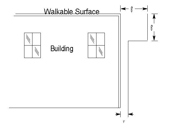
(c) If less than 6 feet below a walkable surface must
have 6 foot horizontal clearance until vertical clearance is obtained.
|
Table 58–2 Ungrounded Cases from Line Conductors (a) (b) |
||||||
|
Line Conductors |
Comm. |
0 - 750 Volts |
750 - 7500 Volts |
7500V - 22.5KV |
22.5 kV & above |
|
|
1 |
Vertical above Case |
48 in. |
3 in.(c) |
12 in.(d) |
18 in. (e) |
24 in. |
|
2 |
Vertical below Case |
48 in. |
10 in.(d) |
12 in.(d) |
18 in. (e) |
24 in. |
|
3 |
Horizontal from Case |
N/A |
6 in. |
12 in. |
18 in. |
24 in. |
Footnotes Modifying Clearances in Table 58–2
(a) For grounded cases see Rule 54.4–G .
(b) For clearances from connecting lead wires and cases, see Table 2, Case 17 .
(c) For conductors supported by rack construction, this dimension shall be a minimum of 4 feet.
(d) May be reduced to 3 inches radially from unenergized cases and hangers, provided no line conductor which is less than 12 inches horizontally from the case or hanger is less than 3 inches above the level of the top surface of the crossarm.
(e)
For transformers see Rule 54.4–D8
.
Strikeout and Underline Version
Rule 58.1
58.1 Enclosed Equipment (Transformers, Capacitors, Regulators, etc.) (For purposes of this rule, enclosed means encased such as with cases or tanks of equipment operated at greater than 750 volts.)
A. Position on Pole
(1) Multiple Units: Where more than one unit is installed on a pole, they shall be placed on the same side of the pole. Transformers installed on metal mounting brackets shall not extend beyond the vertical plane through the centerline of the pole.
(2) Pole Top Extensions: Equipment shall not be supported on pole top extensions.
EXCEPTION: Pole top extensions that conform with strength requirements for a whole pole (see Rule 49.1–A) may be used to support equipment.
B.
Case and Lead Wire
Clearances (See Tables 58–1 & 58–2 )
(1)
Unprotected Lead Wire Clearances:
Unprotected vertical and lateral leads between line conductors and equipment
shall comply with Rules 54.6 and 54.4–C6 ; and with the clearances specified
in Table 1, Cases 8 and 9 ; and
Table 2, Cases 15, 16 and 17 .
Such lead wires may be installed in the working space but shall not be installed
in the climbing space.
The clearance specified in Table
1, Case 8, Columns D and E , need not apply to apparatus installed on poles
consisting of single–pole structures or on crossarms attached thereto, provided
that terminals and lead wires are not less than 6 inches from surface of pole
instead of 3 inches specified in Table 1, Case 9, Columns D and E , and have as much as
possible of the clearances specified in Table 1, Case 8, Columns D and E. No reduction of the
clearances specified in Table 1, Case
8, Columns D and E is permitted for interconnection wiring of polyphase
installations nor to any lead wire passing between pole and apparatus.
(2)
Cases above Ground: Cases of equipment supported on
poles or structures shall be not less than 17 feet above the ground except that
in areas which are not in any way accessible to vehicles, the clearance of cases
above ground may be less than 17 feet provided all cases which are less than 8
feet above ground shall be effectively grounded.
(3)
From Hardware: Equipment cases, hangers, and other
metal parts in contact therewith shall clear through bolts, arm braces of metal,
and other hardware elements, by not less than 1.5 inches; except that such cases
and hangers shall clear crossarm braces and crossarm through bolts by not less
than 1 inch air–gap distance and 1.5 inch creepage distance.
The minimum clearance of 1.5 inches need not apply to through bolts in
metallic contact with equipment cases or metal parts thereof nor to through
bolts supporting heel arms, provided the portion of such through bolts extending
into the climbing space is covered with non–conducting material as specified in
Rule 22.2 .
(4)
From Guys: Equipment cases and their hangers shall
not be less than 4 inches from all portions of guys which are 6 inches or more
from the surface of poles or crossarms at the guy attachments. Such cases and
hangers shall not be less than 1.5 inches from all portions of guys which are
within 6 inches of the surface of poles or crossarms at the guy
attachment.
C.
Equipment Cutouts or Other Equipment Disconnecting
Devices
Equipment cutouts, fuses, disconnects or switches shall be located
so that they are readily accessible from climbing and working spaces. Such
devices or their connecting leads shall not extend into the climbing space, but
may extend into the working space.
The vertical clearance between equipment cutouts, fuses, disconnects or
switches and unprotected conductors of other circuits below shall not be less
than the clearances required between conductors as specified in Table 2, Cases 8 to 13 .
The horizontal clearance between equipment cutouts, fuses, disconnects or
switches and unprotected conductors of different phase or polarity shall not be
less than the clearances specified in Table 2, Case 17 .
The provisions of this rule shall not apply to partial underground
distribution systems.
D.
Ungrounded Case Clearances from Line Conductors (See Table 58–2 )
E. Grounded Case Clearances from Line Conductors (See Rule 54.4–G )
F.
Bonding
Cases of equipment may be bonded together but shall not be bonded to
cutouts, metal pins or deadend
hardware.
|
Table 58–1 Unprotected Bus and Lead Wire Clearances |
|||
|
Case |
Nature of Clearance |
Clearances Required |
|
|
750 Volts - 22.5 kV |
22.5 kV & above |
||
|
Above Ground |
|
|
|
|
1 |
Single Pole Structure |
22.5 Feet |
27.0 Feet |
|
2 |
Two or More Pole Structure |
22.5 Feet (a) |
27.0 Feet (a) |
|
From Buildings - Horizontal |
|
|
|
|
3 |
With Windows, Fire Escapes, etc. |
6.0 Feet (b) |
6.0 Feet |
|
4 |
Without Windows, Fire Escapes, etc. |
1.0 Foot (c) |
1.0 Foot |
|
From Building - Vertical above |
|
|
|
|
5 |
Walkable Surfaces |
12.0 Feet |
12.0 Feet |
|
6 |
Non–Walkable Surfaces |
8.0 Feet |
8.0 Feet |
Footnotes Modifying Clearances in
Table 58–1
(a) May be reduced to 20 feet provided
such lead or bus wires are guarded by transformer platform flooring which
extends not less than 1 foot horizontally outside the vertical planes of all
such lead and bus wires.
(b) May be reduced under special conditions: Supply conductors of 750 - 7,500v see Rule 54.4–H1 .
(c) If less than 6 feet below a walkable surface must
have 6 foot horizontal clearance until vertical clearance is obtained.
|
Table 58–2 Ungrounded Cases from Line Conductors (a) (b) |
||||||
|
Line Conductors |
Comm. |
0 - 750 Volts |
750 - 7500 Volts |
7500V - 22.5KV |
22.5 kV & above |
|
|
1 |
Vertical above Case |
48 in. |
3 in.(c) |
12 in.(d) |
18 in. (e) |
24 in. |
|
2 |
Vertical below Case |
48 in. |
10 in.(d) |
12 in.(d) |
18 in. (e) |
24 in. |
|
3 |
Horizontal from Case |
N/A |
6 in. |
12 in. |
18 in. |
24 in. |
Footnotes Modifying Clearances in Table 58–2
(a) For grounded cases see Rule 54.4–G .
(b) For clearances from connecting lead wires and cases, see Table 2, Case 17 .
(c) For conductors supported by rack construction, this dimension shall be a minimum of 4 feet.
(d) May be reduced to 3 inches radially from unenergized cases and hangers, provided no line conductor which is less than 12 inches horizontally from the case or hanger is less than 3 inches above the level of the top surface of the crossarm.
(e)
For transformers see Rule 54.4–D8
.
Final Version
Rule 58.1
58.1 Enclosed Equipment (Transformers, Capacitors, Regulators, etc.) (For purposes of this rule, enclosed means encased such as with cases or tanks of equipment operated at greater than 750 volts.)
A. Position on Pole
(1) Multiple Units: Where more than one unit is installed on a pole, they shall be placed on the same side of the pole. Transformers installed on metal mounting brackets shall not extend beyond the vertical plane through the centerline of the pole.
(2) Pole Top Extensions: Equipment shall not be supported on pole top extensions.
EXCEPTION: Pole top extensions that conform with strength requirements for a whole pole (see Rule 49.1–A ) may be used to support equipment.
B.
Case and Lead Wire
Clearances (See Tables 58–1 & 58–2 )
(1)
Unprotected Lead Wire Clearances:
Unprotected vertical and lateral leads between line conductors and equipment
shall comply with Rules 54.6 and 54.4–C6 ; and with the clearances specified
in Table 1, Cases 8 and 9 ; and
Table 2, Cases 15, 16 and 17 .
Such lead wires may be installed in the working space but shall not be installed
in the climbing space.
The clearance specified in Table
1, Case 8, Columns D and E , need not apply to apparatus installed on poles
consisting of single–pole structures or on crossarms attached thereto, provided
that terminals and lead wires are not less than 6 inches from surface of pole
instead of 3 inches specified in Table 1, Case 9, Columns D and E , and have as much as
possible of the clearances specified in Table 1, Case 8, Columns D and E. No reduction of the
clearances specified in Table 1, Case
8, Columns D and E is permitted for interconnection wiring of polyphase
installations nor to any lead wire passing between pole and apparatus.
(2)
Cases above Ground: Cases of equipment supported on
poles or structures shall be not less than 17 feet above the ground except that
in areas which are not in any way accessible to vehicles, the clearance of cases
above ground may be less than 17 feet provided all cases which are less than 8
feet above ground shall be effectively grounded.
(3)
From Hardware: Equipment cases, hangers, and other
metal parts in contact therewith shall clear through bolts, arm braces of metal,
and other hardware elements, by not less than 1.5 inches; except that such cases
and hangers shall clear crossarm braces and crossarm through bolts by not less
than 1 inch air–gap distance and 1.5 inch creepage distance.
The minimum clearance of 1.5 inches need not apply to through bolts in
metallic contact with equipment cases or metal parts thereof nor to through
bolts supporting heel arms, provided the portion of such through bolts extending
into the climbing space is covered with non–conducting material as specified in
Rule 22.2 .
(4)
From Guys: Equipment cases and their hangers shall
not be less than 4 inches from all portions of guys which are 6 inches or more
from the surface of poles or crossarms at the guy attachments. Such cases and
hangers shall not be less than 1.5 inches from all portions of guys which are
within 6 inches of the surface of poles or crossarms at the guy
attachment.
C.
Equipment Cutouts or Other Equipment Disconnecting
Devices
Equipment cutouts, fuses, disconnects or switches shall be located
so that they are readily accessible from climbing and working spaces. Such
devices or their connecting leads shall not extend into the climbing space, but
may extend into the working space.
The vertical clearance between equipment cutouts, fuses, disconnects or
switches and unprotected conductors of other circuits below shall not be less
than the clearances required between conductors as specified in Table 2, Cases 8 to 13 .
The horizontal clearance between equipment cutouts, fuses, disconnects or
switches and unprotected conductors of different phase or polarity shall not be
less than the clearances specified in Table 2, Case 17 .
The provisions of this rule shall not apply to partial underground
distribution systems.
D.
Ungrounded Case Clearances from Line Conductors (See Table 58–2 )
E. Grounded Case Clearances from Line Conductors (See Rule 54.4–G )
F.
Bonding
Cases of equipment may be bonded together but shall not be bonded to
cutouts, metal pins or deadend
hardware.
|
Unprotected Bus and Lead Wire Clearances |
|||
|
Case |
Nature of Clearance |
Clearances Required |
|
|
750 Volts - 22.5 kV |
22.5 kV & above |
||
|
Above Ground |
|
|
|
|
1 |
Single Pole Structure |
22.5 Feet |
27.0 Feet |
|
2 |
Two or More Pole Structure |
22.5 Feet (a) |
27.0 Feet (a) |
|
From Buildings - Horizontal |
|
|
|
|
3 |
With Windows, Fire Escapes, etc. |
6.0 Feet (b) |
6.0 Feet |
|
4 |
Without Windows, Fire Escapes, etc. |
1.0 Foot (c) |
1.0 Foot |
|
From Building - Vertical above |
|
|
|
|
5 |
Walkable Surfaces |
12.0 Feet |
12.0 Feet |
|
6 |
Non–Walkable Surfaces |
8.0 Feet |
8.0 Feet |
Footnotes Modifying Clearances in
Table 58–1
(a) May be reduced to 20 feet provided
such lead or bus wires are guarded by transformer platform flooring which
extends not less than 1 foot horizontally outside the vertical planes of all
such lead and bus wires.
(b) May be reduced under special conditions: Supply conductors of 750 - 7,500v see Rule 54.4–H1 .
(c) If less than 6 feet below a walkable surface must
have 6 foot horizontal clearance until vertical clearance is obtained.
|
Ungrounded Cases from Line Conductors (a) (b) |
||||||
|
Line Conductors |
Comm. |
0 - 750 Volts |
750 - 7500 Volts |
7500V - 22.5KV |
22.5 kV & above |
|
|
1 |
Vertical above Case |
48 in. |
3 in.(c) |
12 in.(d) |
18 in. (e) |
24 in. |
|
2 |
Vertical below Case |
48 in. |
10 in.(d) |
12 in.(d) |
18 in. (e) |
24 in. |
|
3 |
Horizontal from Case |
N/A |
6 in. |
12 in. |
18 in. |
24 in. |
Footnotes Modifying Clearances in Table 58–2
(a) For grounded cases see Rule 54.4–G .
(b) For clearances from connecting lead wires and cases, see Table 2, Case 17 .
(c) For conductors supported by rack construction, this dimension shall be a minimum of 4 feet.
(d) May be reduced to 3 inches radially from unenergized cases and hangers, provided no line conductor which is less than 12 inches horizontally from the case or hanger is less than 3 inches above the level of the top surface of the crossarm.
(e)
For transformers see Rule 54.4–D8
.