Original Version
Rule 58
58 Miscellaneous Equipment
58.1 Traffic Signals
Traffic signals supported on overhead suspensions shall be treated as specified in the following rules:
A. Messengers and span wire clearances
The suspension messenger or span wire of all traffic signals shall be installed to afford the clearances prescribed for span wires; Table 1, Column A and Table 2, Column A.
B. Lead wires
Lead Wires of 0-750 volts to traffic signals supported on messengers may be less than the clearances above ground specified in Table 1, Column D, Cases 2 and 3 provided they are maintained at a clearance above ground as specified in Table 1, Column A, Cases 2 and 3 for the messenger on which they are supported.
C. Clearances above thoroughfares
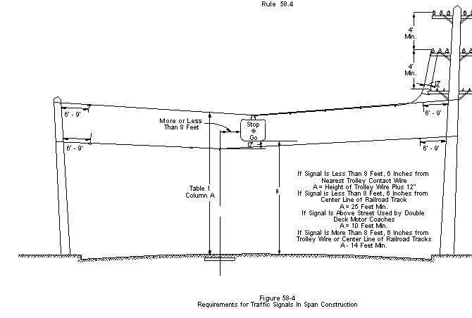
Traffic signals supported by span wires and supplied from circuits of 0-750 volts shall have a clearance of not less than 14 feet vertically above thoroughfares over which they are suspended (see App. G, Fig. 55) except that where any thoroughfares is used by railroads, street railways, trolley coach lines and double deck motor coaches clearances not less than the following shall be maintained:
|
Conveyance using thoroughfare |
Minimum clearance of signal above thoroughfare |
|
Street railways and coach lines operated by overhead trolley-------------------------- |
Height of trolley conductor plus 1 foot (a) |
|
Railroads which transport freight cars---- |
25 feet (b) |
|
Double deck motor coaches |
18 feet |
a) May be reduced to 14 feet if the signal is more than 8 ˝ feet from nearest trolley contact conductor and if signal is maintained not less than 1 foot radially from trolley span wires.
b) May be reduced to 14 feet if signal is more than 8 ˝ feet from center line track.
Traffic signals supplied directly (without protective transformers) from circuits classified in excess of 750 volts shall be install with clearances as prescribed for street lighting equipment.
58.2 Street Lighting Equipment
A.
Circuit Voltage
Constant current series lighting
circuits supplied from transformers or devices having an open circuit output voltage
of more than 750 volts, except those circuits supplied from transformers or
devices having a normal full load output voltage of 750 volts or less which
transformers are equipped with effective protective devices to prevent the
continued existence of open-circuit voltage on the circuit, shall be classified
as circuits of more than 750 volts.
Constant current series lighting
circuits which conform to the specifications for circuits of 0-750 volts may be
installed and treated as circuits of more than 750 volts provided any circuit
so treated in any respect is consistently so treated throughout its entirety.
B. Clearances
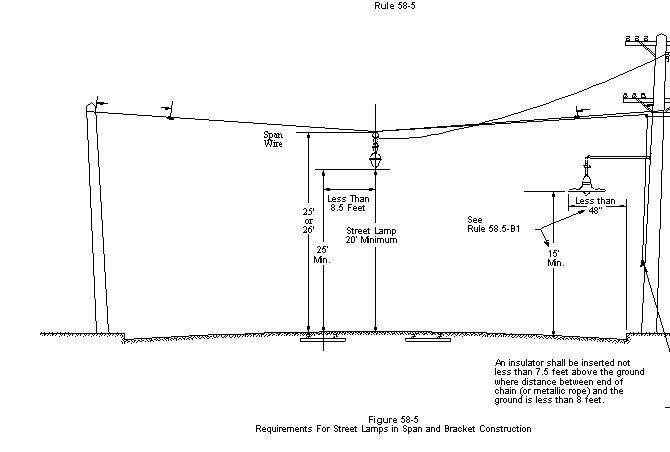
(1) Above Ground: No part of street lighting equipment shall be less than 20 feet above thoroughfares except for lamps supported on brackets or fixtures which do not extend more than 48 inches from the face of pole or street side of curb, in which case the clearances may be reduced to 15 feet, provided the voltage does not exceed 750 volts (see App, G, Fig. 56).
(2)
Above Railways and Trolley Lines: No
part of street lighting equipment which is less than 8 ˝ feet horizontally from
center line of tracks of railroads not operated by overhead trolley shall be
less than 25 feet above such tracks.
No part of street lighting
equipment which is less than 8 ˝ feet horizontally from center line of tracks
or from the nearest trolley contact conductor shall be less than 4 feet above
the level of the trolley contact conductor or less than 23 feet or 26 feet
above running above surfaces used by trolley cars or coaches depending upon the
location of the contact conductors as required by Rule 74.4-B1.
Those parts of street lighting
equipment which are 8 ˝ feet or more horizontally from center line of any
railroad track or any trolley contact conductor shall be not less than 20 feet
above the surface of the thoroughfare, except as provided in Rule 58.2-B1 (see
App. G, Fig. 56).
(3) From Conductors
a) Messengers and Cables: All parts of street light drop wires, street lamps, and their supporting fixtures (including rods, braces, and guys) shall not be less than 1 foot above or 2 feet below the level of messengers or conductors supported by messengers. These vertical clearance requirements shall not apply to those parts of such street lighting equipment which are 2 feet or more horizontally from the vertical plane messengers, conductors supported by messengers, and metal boxes.
b) Conductors not supported by Messengers: All parts of street light drop wires, street lamps, and their supporting fixtures (including rods, braces and guys) shall not be less than 1 foot radially from all unprotected conductors not supported on messengers (including lead wires and taps) except the lead wires supplying the street within 24 inches of their points of entrance to the street lighting equipment.
(4) From Poles: All exposed metal parts of lamps and all such parts of their supports, unless insulated from the parts carrying current, shall be maintained not less than 20 inches from the surface of wood poles, except at pole tops. This rule shall not apply if the voltage of the circuit from which the lamp is supplied does not exceed 750 volts.
C.
Lead wires
Unprotected conductors from one
level on a pole structure to another level or to street lighting equipment
shall not pass within a climbing or working space, and shall not pass within a
climbing or working space, and shall not pass through any other circuit except
between pole pin positions.
Such unprotected conductors
shall clear the conductors of other circuits by distances as specified in Rule
54.6-A.
Where the distance between
levels is in excess of 12 feet and such unprotected conductors pass between the
pole pair of conductors of any other circuit, additional supports shall be
installed so that the maximum length of conductor between supports is not more
than 12 feet.
Unprotected leads to street
lighting equipment shall be maintained at not less than the clearances above
railroads, thoroughfares and ground specified for street lighting equipment in
Rule 58.2-B.
D.
Insulators in Supports
Where a street lighting fixture
is supported by a span wire, strain insulators shall be inserted in the span
wire on both sides of the fixture not more than 9 feet nor less than 6 feet
from the structures supporting the span wire; except that, where such span wire
is used as a trolley for the purpose of drawing the fixture to the pole, the
strain insulator at the service end may be located a distance of not less than
15 inches from the center line of pole.
Where metallic ropes or chains are
used for the suspension of street lamps, said ropes or chains shall be
effectively insulated from current carrying parts of equipment and of such
length that when the lamp is in its normal position the lower end of the chain
or rope will not be less than 8 feet from ground, or a strain insulator shall
be inserted in the free end of the rope or chain at a point not less than 7 ˝
feet from the ground when the lamp is in its normal operation. Metallic ropes
or chains shall be arranged so that they do not establish a metallic conducting
path around a span wire-wire sectionalizing insulator. In case this construction will not permit
the lamp to be lowered sufficiently for trimming purposes, a nonmetallic rope
shall be used.
See App. G,
Fig. 56.
E.
Lighting Units on Transformer Poles
Where a lamp is installed above
a transformer or switch, a minimum vertical separation of 4 feet from any
portion of the transformer or switch and the lighting unit shall be maintained.
Where a lamp is installed below
a transformer, any portion of the lighting equipment shall clear all supply
equipment a minimum distance of 1 foot.
F.
Cutouts
Suitable devices shall be
provided by which each street lamp on series circuits of more than 750 volts
may be safely and entirely disconnected from the circuit, before the lamps are
handled, unless the lamps are worked on from wood poles or from suitable
insulating stools, platforms or tower wagons.
Exempted from this provision are lamps such as incandescent lamps which
in themselves present a noncurrent-carrying surface which may be utilized as a
handle in removing them from their support.
F.
Exceptions
Lighting units supported on
ornamental posts and supplied from underground sources are not included herein.
58.3 Transformers
A.
Position on Pole
Where more than one transformer
is installed on a pole, all transformers shall be placed on the same side of
pole.
Transformers
shall not be supported on pole top extensions.
B. Case and Lead wire Clearances
(1) Above Ground
a)
Lead and bus wires: The clearances
above ground specified in Table 1 are applicable to unprotected lead and bus
wires of transformer installations except as modified by the following
provisions.
Clearances above ground unprotected lead and bus wires of
transformer installations may be less than 25 feet as specified in Table 1,
Column E case 3 and 4, but shall not be less than 22 ˝ feet except where a
clearance of not less than 18 feet above ground is permitted by the provisions
of Rule 54.4-A2b in which case the clearance above ground of such lead and bus
wires shall be not less than 18 feet,
Clearances
above ground of unprotected lead and bus wires of transformer installations may
be less than 30 feet as specified in Table 1, Column F, Cases 3 and 4, but
shall be not less than 27 feet.
Clearances
above ground of unprotected lead and bus wires of transformer installations on
structures of two or more poles may be less than 22 ˝ feet or 27 feet as
specified above, or less than 25 feet as specified in Table 1, Column F, Case 5
but shall not be less than 20 feet above ground, provided such lead or bus
wires are guarded by transformer platform flooring which extends not less than
1 foot horizontally outside the vertical planes of all such lead and bus wires
on the structure.
b) Cases: Cases of transformers supported on poles or structures shall not be less than 17 feet above the ground except that in areas which are not in any way accessible to vehicles, the clearance of cases above ground shall be effectively grounded.
(2)
From Buildings: Transformers on poles
shall be so located that normally Unenergized parts clear the surfaces of
buildings by not less than 3 feet horizontally or by not less than 8 feet
vertically. Lead and bus wires carried
as unprotected conductors shall have the clearances from buildings as specified
in Table 1, Cases 6 and 7.
In situations where foregoing
clearances of cases and lead bus wires from walls of buildings (not windows,
fire escapes, etc.) are impracticable to obtain, such as the location of transformers
on poles in alleys, these clearances will not be held applicable provided wood
barriers authorized by this Commission are used.
(3) Cases from conductor levels above and below: Transformers shall be so installed that normally Unenergized metal parts clear unprotected conductors, except the transformer connecting leads by distances specified in the following provisions:
a) From 0-750 volt conductors below: The vertical clearance of transformer cases and hangers from the level of 0-750 volt conductors below (whether such conductors are supported on crossarms or racks) shall not be less than 10 inches except for certain conductors as provided in Rule 58.3-B4.
b) From 0-750 volt conductors above: The vertical clearance of Unenergized metal parts of transformers from 0-750 volt conductors supported on crossarms above shall be not less than 3 inches or, in lieu of such vertical clearance, the Unenergized parts of transformers shall not be less than 6 inches horizontally from such conductors. The vertical clearance of unenergized metal parts of transformers from 0-750 volt conductors supported on racks above shall be not less than 4 feet.
c) From 750-7500 volt conductors below: The vertical clearance of Unenergized metal parts of transformers from the level of 750-7500 volt conductors below shall be not less than 12 inches.
d) From 750-7,500 Volt Conductors Above: The clearance between un-energized metal parts of transformers and 750-7,500 volt conductors above or alongside shall be not less than 12 inches vertically or 12 inches horizontally, except that conductors of the circuit to which the transformer is connected may be less than the 12-inch vertical clearance from such un-energized parts but shall be not less than 6 inches vertically from the transformer case and not less than 3 inches radially from the hanger provided no line conductor which is less than 12 inches horizontally from the case or hanger is less than 3 inches (Table 1, Case 9) above the level of the top surface of the crossarm.
EXCEPTION: The vertical clearance shall not be less than 30 inches from the conductor at the top of pole as in Rule 54.4-D8.
e) From 7,500-22,500 Volt Conductors Above: The clearance between un-energized metal parts of transformers and 7,500-22,500 volt conductors above shall be not less than 18 inches vertically or 18 inches horizontally.
EXCEPTION: The vertical clearance shall not be less than 30 inches from a conductor at the top of pole as in Rule 54.4-D8.
(4) Transformer Cases from Certain Conductors Less than 10 inches below the cases
a) Transformer Leads on Heel Arms: Heel arms shall not used to support lead wires or taps except where necessary to clear the lower voltage transformer leads from the transformer case or other conductors.
b) Line conductors less than 10 inches below cases: Where a transformer case is unusually long, a crossarm supporting line conductors of 0-750 volts may be used as a heel arm or such conductors on an arm may be less than 10 inches below the transformer case or the hangers) provided all of the following conditions are met:
No more than a single transformer with lower voltage of 0-750 volts is supported on the pole at the same level;
The vertical clearances between conductors on the hanger arm and such line arm below shall not be less than as specified in Table 2, Cases 9 to 13;
It is not practicable to obtain the clearance of at least 10 inches specified in Rule 58.3-B3;
Such 0-750 volt conductors clear the transformer case by not less than 15 inches horizontally;
Service drops are not run from the crossarm supporting 0-750 volts conductors at that location; and
The vertical clearance of 0-750 volt conductors below the lowest point of the transformer primary leads is not less than
18 inches for primary leads of 750-7500 volts,
24 inches for primary leads of 7500-20,000 volts,
36 inches for primary leads of 20,000-35,000 volts.
(5)
From Hardware: Transformer cases,
hangers, and other metal parts in contact therewith shall clear through bolts,
arm braces and other hardware by not less than 1 ˝ inches; except that
transformer cases and hangers shall clear crossarm braces and crossarm through
bolts by not less than 1-inch air-gap distances and 1 ˝ –inch creepage
distance.
The minimum clearance of 1 ˝
inches need not apply to through bolts in metallic contact with transformer
cases or metal parts thereof nor to through bolts supporting heel arms,
provided the portion of such through bolts extending into the climbing space is
covered with a suitable protective covering, and provided that such coverings
are made of seasoned Douglas Fir and are installed in a workmanlike manner, or
in the alternative, with a suitable nonconducting shield or covering having the
insulation efficiency and mechanical strength of impregnated fiber 5/16 inches
thick.
(6) From Guys: Transformer cases and hangers shall be not less than 4 inches from all portions of guys which are 6 inches or more from the surface of poles or crossams at the guy attachment. Transformer cases and hangers shall be not less than 1 ˝ inches from all portions of guys which are within 6 inches of the surface of poles or crossarms at the guy attachments.
(7)
Treatment of lead wires: Vertical and
lateral leads between line conductors and transformers shall comply with Rule
54.6 and 54.4-C6; and with the clearances specified in Table 1, Cases 8 and 9;
and Table 2, Cases 15, 16 and 17. Where
such leads enter cutouts or switches Rule 58.5-C shall also apply. Such lead wires may be installed in the
climbing space.
The clearances specified in
Table 1, Case 8, Column D and E need not apply to apparatus installed on poles
consisting of single pole structures or on crossarms attached thereto provided
that terminals and lead wires are not less than 6 inches from surface of pole
instead of 3 inches specified in Table 1, Case 9, Columns D and E, and have as
much possible of the clearance specified in Table 1, Case 8 Columns D and E, is
permitted for interconnection wiring of polyphase installations nor to
connection wiring of polyphase installations nor to any lead wire passing
between pole apparatus.
All lead
wires shall clear braces, bolts and other line hardware a distance of not less
than 1 ˝ inches.
C. Grounding
(1) Grounding of Windings: Transformer windings not exceeding 250 volts (except those exclusively for energizing street lighting circuits and those used exclusively for energizing signal and track circuit) shall be effectively grounded as follows:
a) Single phase systems: In two wire (nominal 120-volt system one wire shall be grounded; in two wire (nominal 240-volt) systems where the mid-point or some intermediate point of the windings is not available, one wire shall be grounded; in two-wire (nominal 240 volt) systems where the mid-point or some intermediate point of the winding is available, that point shall be grounded; in three-wire (nominal 120/240-volt) systems, the mid-point of the winding shall be grounded. (See App. G, Fig 57.)
b) Two phase systems: In three-wire (nominal 240 volt) systems, the point common to both windings shall be grounded; in four-wire (nominal 120/240-volt) systems, the mid-point of the winding on one phase shall be grounded; in four wire (nominal 240-volt), and five wire (nominal 120/240-votls) systems, the mid-points of both windings shall be connected and grounded. (See App. G, Fig. 58.)
c) Three-Phase Systems: In three-wire delta (nominal 120 or 240 volt) systems the midpoint of one transformer winding or, a point common to two windings (one phase wire) shall be grounded; in three-wire star (nominal 120 208or 240 volt) systems, the point common to all windings or, one of the phase wires shall be grounded; in four-wire star (nominal 120/208 volt) systems, the common point shall be grounded (see App. G, Fig. 59).
d) Where the Secondary system is grounded at any point, the grounded conductor shall be run to each service.
(2) Location of Transformer Winding Grounds: Transformer ground connections shall be provided at one of the following locations:
At the transformer pole,
At a pole adjacent to the transformer pole, or
AT the load end of each service supplied from the transformer, separate from the usual house ground, except that where three or more services are supplied from one transformer or bank of transformers, ground connections at the two services nearest the transformer pole and one ground connection at services at approximately 500-foot intervals will suffice.
Transformer ground connections other than those occurring on common primary and secondary grounded neutral systems shall have a conductivity not less than that of No. 6 AWG copper wire.
Where a common primary and secondary grounded neutral system is used, ground connections shall conform to the requirements of Rule 59.4-A.
(3)
Transformer Case Grounding or Bonding:
Cases of transformers and metal parts in contact therewith shall not be
grounded where supported on wood poles or wood structures.
Except in the case of partial
underground distribution systems (see Rule 21.13),the hanging or placing of
transformers on metal poles or structures is not recommended, particularly with
respect to transformers connected to circuits of less than 14,000 volts. Transformers shall not be supported on metal
poles or metal supports in contact with the ground unless the cases are
securely bonded to the metal poles or parts of structures in contact with the
ground and such poles or structures are effectively grounded. No transformer case shall be in contact with
a metal support (crossarm, metal beam. metal bracket) attached to a wood pole
or a wood structure, excepting when no portion of a transformer case or its
metal support extends beyond a vertical plane through the center line of pole.
The bonding of cases of
transformers whose high voltage windings are connected to circuits of less than
20,000 volts is not recommended but where such cases are bonded the case
bonding system shall not be electrically connected to any unassociated hardware
or to other bonds.
Except from the provisions of
this Rule 58.3-C3 applying to the grounding of transformer cases supported on
wood poles or structures are the following:
Any
transformer whose high-voltage winding is connected to a circuit of more than
14,000 volts, which may have its case grounded provided all such transformer
installations on the system are so grounded, warning signs calling attention to
the case grounding condition are posted on the structure so as to be readily
legible from the climbing space or spaces, and no such grounded transformer
case is less than 8 feet vertically or 4 feet horizontally from the unprotected
conductors of any other supply-line circuit than those to which the transformer
windings are connected;
Any transformer whose high-voltage is connected to a circuit of 750-14,000 volts, which may have its case grounded provided no unprotected conductors (including lead wires) of 750-14,000 volts shall be less than 8 feet vertically or 4 feet horizontally from the nearest part of such grounded case; and
Any transformer the case of which is less than 8 feet above the ground.
Transformer cases which are grounded in accordance with any provision of this rule shall be effectively grounded (see Rule 33.3).
D.
Cutouts or Other Disconnecting Devices
Transformer cutouts, fuses,
disconnects or switches shall be located so that they are readily accessible
from climbing and working spaces. Such devices or their connecting leads
shall not extend into the climbing space but may extend wholly or in part into
the working space.
The vertical clearances of transformer cutouts, fuses, etc., above the levels
of conductors of other circuits shall not less than the clearances required
between conductors as specified in Table 2, Cases 8 to 13.
The provisions of this rule shall not apply to partial underground distribution
systems.
E.
Connections Between Windings
Any metallic connection between
the primary and secondary windings of a distribution transformer (as in common
neutral systems) shall be made externally and not within the transformer case.
58.4 Capacitors and Voltage Regulators
A.
Position on Pole
Where more than one capacitor or
regulator is installed on a pole, all capacitors or regulators shall be placed
on the same side of the pole. Excepted
from this requirement are capacitors which may be installed on opposite sides
of a pole between the two arms of a double arm provided no transformers,
regulators, or oil switches are installed on the same pole.
Capacitors or regulators shall
not be installed on pole top extensions.
B. Case and Lead wire Clearances
(1) Above ground: Any capacitor or regulator shall be so located that the bottom of the case and associated metal parts shall not be less than 17 feet above ground. The clearances above ground of leads to such apparatus shall conform to the requirements of Rule 58.3-B1a.
(2) From Buildings: Capacitors or regulators shall be so located that normally unenergized parts clear the surfaces of buildings by not less than 3 feet horizontally or by not less than 8 feet vertically. Lead and bus wires carried as unprotected conductors shall have the clearances from building specified in Table 1, Cases 6 and 7.
(3) Cases From Conductor levels below
a) From 0-750 Volt Conductors Below: The vertical clearance of capacitor and regulator cases and their hangers from the level of 0-750 volt conductors below (whether such conductors are on crossarms or racks) shall not be less than 10 inches.
b) From Conductors in Excess of 750 Volts Below: The vertical clearance of capacitor and regulator cases and their hangers from the level of conductors in excess of 750 volts below shall be not less than
12 inches for conductors of 750-7500 volts,
18 inches for conductors of 7500-20,000 volts, and
24 inches for conductors of 20,000-35,000 volts.
(4) From Hardware: Capacitor or regulator cases hangers, and other metal parts in contact therewith shall clear through bolts, arm braces of metal, and other hardware elements, by not less than 1 ˝ inches; except that such cases shall clear crossarm braces by not less than 1-inch air-gap distance and 1 1/2 –inch creepage distance.
(5) From Guys: Capacitor or regulator cases and their hangers shall be not less than 4 inches from all portions of guys which are 6 inches or more from the surface of poles or crossarms at the guy attachments. Such cases and hangers shall be not less than 1 ˝ inches from all portions of guys which are within 6 inches of the surface of poles or crossarms at the guy attachment.
(6)
Treatment of Lead Wires: Vertical and
lateral leads between line conductors and capacitors or regulators shall comply
with Rules 54.6 and 54.4-C6; and with the clearances specified in Table 1,
Cases 8 and 9; and Table 2, Cases 15, 16, and 17. Where such leads enter
cutouts or switches, Rule 58.5-C shall also apply. Vertical and lateral
leads between cutouts or fuse holders and regulator bushings, or leads directly
between line conductors and such bushings may clearances less than those
specified in Table 1, Case 8 Columns E and F, but not less than 6 inches from
the surface of the pole; such leads shall not be over 12 inches in length.
Such lead wires may be installed in the working space but shall not be
installed in the climbing space.
The clearances
specified in Table 1, Case 8, Columns D and E, need not apply to apparatus
installed on poles consisting of single-pole structures or on crossarms
attached thereto provided that terminals and lead wires are not less than 6
inches from surface of pole instead of 3 inches specified in Table 1, Case 9
Columns D and E, and have as mush possible of the clearances specified in Table
1, Case 8, Columns D and E. No reduction of the clearances specified in
Table 1, Case 8, Columns D and E is permitted for interconnection wiring of
polyphase installations nor to any lead wire passing between pole and
apparatus.
All lead wires shall
clear braces, bolts and other line hardware a distance of not less than 1 ˝
inches.
C.
Grounding and Bonding of Capacitors or
Regulators
Cases of capacitors or
regulators may be bonded together but shall not be bonded to cutout, metal
pins, or dead-end hardware.
Cases of Capacitors shall not be
grounded where such cases or any parts therof are within 8 feet vertically
below, 4 feet vertically above 4 feet horizontally from any unprotected
conductors.
Any capacitors or regulator
which may be grounded in accordance with any provision of this rule shall be
effectively grounded (see Rule 33.3).
D.
Cutouts or Other Disconnecting Devices
Cutouts, fuses, disconnects or
switches used in connection with capacitors or regulators shall be so located
so that they are readily accessible from climbing and working spaces. Such devices or their connecting leads shall
not extend into the climbing space, but may extend wholly or in part into the
working space.
The vertical clearances of
capacitor or regulator cutouts, fuses, etc., above the levels of conductors of
other circuits shall be not less than the clearances required between
conductors as specified in Table 2, Cases 8 to 13.
58.5 Line Switches and Disconnects
A.
Clearance Between Energized Parts
Unenclosed switches supported on
poles or pole structures shall be arranged with clearances not less than as
specified in Table 2, Case 15 between the center lines of the separate phase
units.
Unenclosed switches supported on
poles or pole structures shall be arranged with clearances not less than as
specified in Table 2, Case 17 between exposed parts which are energized from
the same circuit from different phases or polarities.
B.
Clearance Between Unenergized Parts
and Unprotected Conductors
Metal switch cases and normally
Unenergized metal parts in contact therewith shall clear all unprotected
conductors, except the connecting leads, by distances as specified in Rule
58.3-B3 for Unenergized metal parts of transformers from unprotected
conductors.
C.
Lead Wires
Lead wires shall be suitably
insulated from metal or wood cases of cutouts and switches at point of entrance
thereto.
All unprotected lead wires
including miscellaneous wiring shall clear brace, bolts and other line hardware
a distance of not less than 1 ˝ inches.
Where necessary at points of
entrance to cutouts and switches, lead wires of 0-5000 volts may be less than 3
inches from the surface of crossarms (Table 1, Case 9, Column C, D, and E) but
shall be not less than 1 inch from such surfaces.
D.
Climbing and Working Space
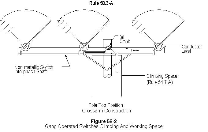
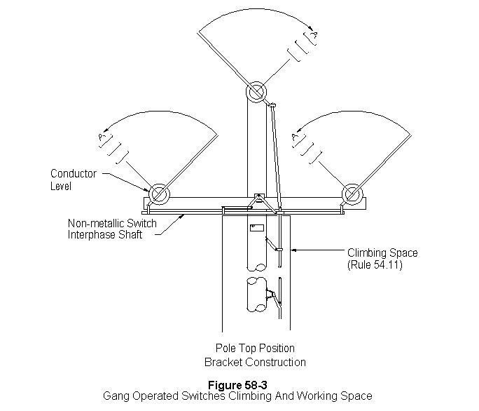
Switches and cutouts shall be so located that, when in either the open
or closed position, all energized parts thereof are not less than 15 or 18
inches from the centerline of pole as required by Table 1, Case 8, and no part
of such equipment shall be in the climbing space except nonmetallic interphase
shafts of gang operated switches and their associated unbonded hardware mounted
at the top of the pole. See figures
58-1 and 58-2. Such apparatus is
permitted to be wholly or in part within the working space. The clearances of
15 or 18 inches need not apply to nonfusable pole-top switches connected to a
circuit of 7,500 volts or more, provided the switches are installed
substantially in the same vertical plane as the conductors to which they are
attached, and no climbing space has to be provided through and above the level
of such switches.
E.
Indicating Position
All enclosed switched shall
indicate clearly whether they are in the open or closed position.
F. Grounding (see Rule 52.7-F)
G.
Operating Mechanism
Grounded metal operating rods
which pass through conductor levels shall be protected with a suitable
insulating covering for a distance of 8 feet vertically or 6 feet horizontally
from communication conductors (including cables) and from unprotected supply
conductors. As an alternative to this
provision, metal rods shall be underground and shall have installed in them, at
a point as near as possible to the switch, a suitable insulating link or
section. All rods shall be securely
held in position by staples or straps or other suitable means to afford
clearances as specified in Table 2, Case 18 from conductors of circuits below
the switch level.
All cables, ropes and other
flexible means of operating switches shall have insulators installed in them at
a point as close as possible to the switch and shall pass through guides to
insure their separation from conductors through which they pass.
Where line switches are operated
from the ground level by means of all metal control mechanisms without suitable
insulating links, an insulated platform shall be provided unless such operating
mechanism is effectively grounded.
58.6 Time Switches, Meters, Metal Boxes and Other Apparatus
A.
Location and Clearances from
Transformer, Capacitor or Regulator Cases
Time switches, meters and other
apparatus, including their enclosures, which extend more than 5 inches from the
surface of a pole shall not be installed on the surface of a pole shall not be
installed on the surface of a pole supporting a transformer (or other equipment
of similar dimensions), shall be not less than 4 feet above or below the
nearest part of transformer case (or other equipment), unless the time switch,
meter, etc., is installed on the side of the pole occupied by the transformer
(or other equipment).
B.
Clearance from Unprotected Conductors
On wood poles or structures, all
grounded metal boxes and grounded metal cases for time switches, meters, or
other apparatus shall be not less than 3 feet above or 6 feet below the level
of unprotected supply conductors. Where
it is impracticable to obtain a clearance of at least 6 feet below the level of
unprotected supply conductors of 750 volts or less, a clearance of not less
than 4 feet below such conductors will be permitted if a protective covering or
guard is provided above the grounded surface.
C.
Within 8 feet of the ground
Boxes or enclosures containing
switches, meters, or other apparatus having accessible live parts, which are
located 8 feet or less above the ground shall be effectively locked or sealed.
Metal Boxes which contain supply
or control equipment or conductors and are located 8 feet or less above the
ground shall be effectively grounded.
Strikeout and Underline Version
Rule 58
58 Miscellaneous Equipment
58.14
Traffic Signals
Traffic signals supported on overhead suspensions shall be treated as specified in the following rules:
A.
Messengers and span wire clearances
The suspension messenger or span
wire of all traffic signals shall be installed to afford the clearances
prescribed for span wires; Table 1, Column A and Table 2, Column A.
B.
Lead wires
Lead Wires of 0-750 volts to
traffic signals supported on messengers may be less than the clearances above
ground specified in Table 1, Column D, Cases 2 and 3 provided they are
maintained at a clearance above ground as specified in Table 1, Column A, Cases
2 and 3 for the messenger on which they are supported.
C.
Clearances above thoroughfares
Traffic signals supported by
span wires and supplied from circuits of 0-750 volts shall have a clearance of
not less than 14 feet vertically above thoroughfares over which they are
suspended (see App. G, Fig. 55 Fig. 58-4) except that where any
thoroughfares is used by railroads, street railways, trolley coach lines and
double deck motor coaches clearances not less than the following shall be
maintained:
|
Conveyance using thoroughfare |
Minimum clearance of signal above thoroughfare |
|
Street railways and coach lines operated by overhead trolley-------------------------- |
Height of trolley conductor plus 1 foot (a) |
|
Railroads which transport freight cars---- |
25 feet (b) |
|
Double deck motor coaches |
18 feet |
a) May be reduced to 14 feet if the signal is more than 8 ˝ feet from nearest trolley contact conductor and if signal is maintained not less than 1 foot radially from trolley span wires.
b) May be reduced to 14 feet if signal is more than 8 ˝ feet from center line track.
Traffic signals supplied directly (without protective transformers) from circuits classified in excess of 750 volts shall be install with clearances as prescribed for street lighting equipment.
58.25
Street Lighting Equipment
A.
Circuit Voltage
Constant current series lighting
circuits supplied from transformers or devices having an open circuit output
voltage of more than 750 volts, except those circuits supplied from transformers
or devices having a normal full load output voltage of 750 volts or less which
transformers are equipped with effective protective devices to prevent the
continued existence of open-circuit voltage on the circuit, shall be classified
as circuits of more than 750 volts.
Constant current series lighting
circuits which conform to the specifications for circuits of 0-750 volts may be
installed and treated as circuits of more than 750 volts provided any circuit
so treated in any respect is consistently so treated throughout its entirety.
B. Clearances
(1)
Above Ground: No part of street lighting
equipment shall be less than 20 feet above thoroughfares except for lamps
supported on brackets or fixtures which do not extend more than 48 inches from
the face of pole or street side of curb, in which case the clearances may be
reduced to 15 feet, provided the voltage does not exceed 750 volts (see App,
G, Fig. 56 Fig. 58-6).
(2)
Above Railways and Trolley Lines: No
part of street lighting equipment which is less than 8 ˝ feet horizontally from
center line of tracks of railroads not operated by overhead trolley shall be
less than 25 feet above such tracks.
No part of street lighting
equipment which is less than 8 ˝ feet horizontally from center line of tracks
or from the nearest trolley contact conductor shall be less than 4 feet above
the level of the trolley contact conductor or less than 23 feet or 26 feet
above running above surfaces used by trolley cars or coaches depending upon the
location of the contact conductors as required by Rule 74.4-B1.
Those parts of street lighting
equipment which are 8 ˝ feet or more horizontally from center line of any
railroad track or any trolley contact conductor shall be not be
less than 20 feet above the surface of the thoroughfare, except as provided in
Rule 58.25-B1 (see App, G, Fig. 56 Fig. 58-6).
(3) From Conductors
a) Messengers and Cables: All parts of street light drop wires, street lamps, and their supporting fixtures (including rods, braces, and guys) shall not be less than 1 foot above or 2 feet below the level of messengers or conductors supported by messengers. These vertical clearance requirements shall not apply to those parts of such street lighting equipment which are 2 feet or more horizontally from the vertical plane messengers, conductors supported by messengers, and metal boxes.
b) Conductors not supported by Messengers: All parts of street light drop wires, street lamps, and their supporting fixtures (including rods, braces and guys) shall not be less than 1 foot radially from all unprotected conductors not supported on messengers (including lead wires and taps) except the lead wires supplying the street within 24 inches of their points of entrance to the street lighting equipment.
(4) From Poles: All exposed metal parts of lamps and all such parts of their supports, unless insulated from the parts carrying current, shall be maintained not less than 20 inches from the surface of wood poles, except at pole tops. This rule shall not apply if the voltage of the circuit from which the lamp is supplied does not exceed 750 volts.
C.
Lead wires
Unprotected conductors from one
level on a pole structure to another level or to street lighting equipment
shall not pass within a climbing or working space, and shall not pass within a
climbing or working space, and shall not pass through any other circuit except
between pole pin positions.
Such unprotected conductors
shall clear the conductors of other circuits by distances as specified in Rule
54.6-A.
Where the distance between
levels is in excess of 12 feet and such unprotected conductors pass between the
pole pair of conductors of any other circuit, additional supports shall be
installed so that the maximum length of conductor between supports is not more
than 12 feet.
Unprotected leads to street
lighting equipment shall be maintained at not less than the clearances above
railroads, thoroughfares and ground specified for street lighting equipment in
Rule 58.25-B.
D.
Insulators in Supports
Where a street lighting fixture
is supported by a span wire, strain insulators shall be inserted in the span
wire on both sides of the fixture not more than 9 feet nor less than 6 feet
from the structures supporting the span wire; except that, where such span wire
is used as a trolley for the purpose of drawing the fixture to the pole, the
strain insulator at the service end may be located a distance of not less than
15 inches from the center line of pole.
Where metallic ropes or chains
are used for the suspension of street lamps, said ropes or chains shall be
effectively insulated from current carrying parts of equipment and of such
length that when the lamp is in its normal position the lower end of the chain
or rope will not be less than 8 feet from ground, or a strain insulator shall be
inserted in the free end of the rope or chain at a point not less than 7 ˝ feet
from the ground when the lamp is in its normal operation. Metallic ropes or
chains shall be arranged so that they do not establish a metallic conducting
path around a span wire-wire sectionalizing insulator. In case this construction will not permit
the lamp to be lowered sufficiently for trimming purposes, a nonmetallic rope
shall be used.
See App. G,
Fig. 56 Fig 58-6.
E.
Lighting Units on Transformer Poles
Where a lamp is installed
above a transformer or switch, a minimum vertical separation of 4 feet from any
portion of the transformer or switch and the lighting unit shall be maintained.
Where a lamp is installed
below a transformer, any portion of the lighting equipment shall clear all
supply equipment a minimum distance of 1 foot.
|
1) Lighting units above |
4 feet |
|
2) Lighting units below |
1 foot |
F.
Cutouts
Suitable devices shall be
provided by which each street lamp on series circuits of more than 750 volts
may be safely and entirely disconnected from the circuit, before the lamps are
handled, unless the lamps are worked on from wood poles or from suitable
insulating stools, platforms or tower wagons.
Exempted from this provision are lamps such as incandescent lamps which
in themselves present a noncurrent-carrying surface which may be utilized as a
handle in removing them from their support.
G.
Exceptions
Lighting units supported on
ornamental posts and supplied from underground sources are not included herein.
58.32
Transformers
A.
Position on Pole
Where more than one
transformer is installed on a pole, all transformers shall be placed on the
same side of pole.
Transformers
shall not be supported on pole top extensions.
B.
Case and Lead wire Clearances
(1)
Above Ground
a)
Lead and bus wires: The clearances above
ground specified in Table 1 are applicable to unprotected lead and bus wires of
transformer installations except as modified by the following provisions.
Clearances above ground unprotected lead and bus wires of
transformer installations may be less than 25 feet as specified in Table 1,
Column E case 3 and 4, but shall not be less than 22 ˝ feet except where a
clearance of not less than 18 feet above ground is permitted by the provisions
of Rule 54.4-A2b in which case the clearance above ground of such lead and bus
wires shall be not less than 18 feet,
Clearances
above ground of unprotected lead and bus wires of transformer installations may
be less than 30 feet as specified in Table 1, Column F, Cases 3 and 4, but
shall be not less than 27 feet.
Clearances
above ground of unprotected lead and bus wires of transformer installations on
structures of two or more poles may be less than 22 ˝ feet or 27 feet as
specified above, or less than 25 feet as specified in Table 1, Column F, Case 5
but shall not be less than 20 feet above ground, provided such lead or bus
wires are guarded by transformer platform flooring which extends not less than
1 foot horizontally outside the vertical planes of all such lead and bus wires
on the structure.
b)
Cases: cases of transformers supported on
poles or structures shall not be less than 17 feet above the ground except that
in areas which are not in any way accessible to vehicles, the clearance of
cases above ground shall be effectively grounded.
(2)
From Buildings: Transformers on poles
shall be so located that normally Unenergized parts clear the surfaces of buildings
by not less than 3 feet horizontally or by not less than 8 feet
vertically. Lead and bus wires carried
as unprotected conductors shall have the clearances from buildings as specified
in Table 1, Cases 6 and 7.
In situations where foregoing
clearances of cases and lead bus wires from walls of buildings (not windows,
fire escapes, etc.) are impracticable to obtain, such as the location of
transformers on poles in alleys, these clearances will not be held applicable
provided wood barriers authorized by this Commission are used.
(3)
Cases from conductor levels above and
below: Transformers shall be so installed that normally Unenergized metal parts
clear unprotected conductors, except the transformer connecting leads by
distances specified in the following provisions:
a)
From 0-750 volt conductors below: The
vertical clearance of transformer cases and hangers from the level of 0-750
volt conductors below (whether such conductors are supported on crossarms or
racks) shall not be less than 10 inches except for certain conductors as
provided in Rule 58.3-B4.
b)
From 0-750 volt conductors above: The
vertical clearance of Unenergized metal parts of transformers from 0-750 volt
conductors supported on crossarms above shall be not less than 3 inches or, in
lieu of such vertical clearance, the Unenergized parts of transformers shall
not be less than 6 inches horizontally from such conductors. The vertical clearance of unenergized metal
parts of transformers from 0-750 volt conductors supported on racks above shall
be not less than 4 feet.
c)
From 750-7500 volt
conductors below: The vertical clearance of Unenergized metal parts of
transformers from the level of 750-7500 volt conductors below shall be not less
than 12 inches.
d)
From 750-7,500 Volt Conductors Above: The
clearance between un-energized metal parts of transformers and 750-7,500 volt
conductors above or alongside shall be not less than 12 inches vertically or 12
inches horizontally, except that conductors of the circuit to which the
transformer is connected may be less than the 12-inch vertical clearance from
such un-energized parts but shall be not less than 6 inches vertically from the
transformer case and not less than 3 inches radially from the hanger provided
no line conductor which is less than 12 inches horizontally from the case or
hanger is less than 3 inches (Table 1, Case 9) above the level of the top
surface of the crossarm.
EXCEPTION:
The vertical clearance shall not be less than
30 inches from the conductor at the top of pole as in Rule 54.4-D8.
e)
From 7,500-22,500 Volt
Conductors Above: The clearance between un-energized metal parts of
transformers and 7,500-22,500 volt conductors above shall be not less than 18
inches vertically or 18 inches horizontally.
EXCEPTION:
The
vertical clearance shall not be less than 30 inches from a conductor at the top
of pole as in Rule 54.4-D8.
(4)
Transformer Cases from Certain
Conductors Less than 10 inches below the cases
a)
Transformer Leads on Heel Arms: Heel arms
shall not used to support lead wires or taps except where necessary to clear
the lower voltage transformer leads from the transformer case or other
conductors.
b)
Line conductors less than 10 inches below
cases: Where a transformer case is unusually long, a crossarm supporting line
conductors of 0-750 volts may be used as a heel arm or such conductors on an
arm may be less than 10 inches below the transformer case or the hangers)
provided all of the following conditions are met:
No more than a single
transformer with lower voltage of 0-750 volts is supported on the pole at the
same level;
The vertical clearances
between conductors on the hanger arm and such line arm below shall not be less
than as specified in Table 2, Cases 9 to 13;
It is not practicable to
obtain the clearance of at least 10 inches specified in Rule 58.3-B3;
Such 0-750 volt conductors
clear the transformer case by not less than 15 inches horizontally;
Service drops are not run
from the crossarm supporting 0-750 volts conductors at that location; and
The vertical clearance of
0-750 volt conductors below the lowest point of the transformer primary leads
is not less than
18 inches for primary leads
of 750-7500 volts,
24 inches for primary leads
of 7500-20,000 volts,
36 inches for primary leads of 20,000-35,000 volts.
(5)
From Hardware: Transformer cases,
hangers, and other metal parts in contact therewith shall clear through bolts,
arm braces and other hardware by not less than 1 ˝ inches; except that
transformer cases and hangers shall clear crossarm braces and crossarm through
bolts by not less than 1-inch air-gap distances and 1 ˝ –inch creepage
distance.
The minimum clearance of 1 ˝
inches need not apply to through bolts in metallic contact with transformer
cases or metal parts thereof nor to through bolts supporting heel arms,
provided the portion of such through bolts extending into the climbing space is
covered with a suitable protective covering, and provided that such coverings
are made of seasoned Douglas Fir and are installed in a workmanlike manner, or
in the alternative, with a suitable nonconducting shield or covering having the
insulation efficiency and mechanical strength of impregnated fiber 5/16 inches
thick.
(6)
From Guys:
Transformer cases and hangers shall be not less than 4 inches from all portions
of guys which are 6 inches or more from the surface of poles or crossams at the
guy attachment. Transformer cases and
hangers shall be not less than 1 ˝ inches from all portions of guys which are
within 6 inches of the surface of poles or crossarms at the guy attachments.
(7)
Treatment of lead wires: Vertical and
lateral leads between line conductors and transformers shall comply with Rule
54.6 and 54.4-C6; and with the clearances specified in Table 1, Cases 8 and 9;
and Table 2, Cases 15, 16 and 17. Where
such leads enter cutouts or switches Rule 58.5-C shall also apply. Such lead wires may be installed in the
climbing space.
The clearances specified in
Table 1, Case 8, Column D and E need not apply to apparatus installed on poles
consisting of single pole structures or on crossarms attached thereto provided
that terminals and lead wires are not less than 6 inches from surface of pole
instead of 3 inches specified in Table 1, Case 9, Columns D and E, and have as
much possible of the clearance specified in Table 1, Case 8 Columns D and E, is
permitted for interconnection wiring of polyphase installations nor to
connection wiring of polyphase installations nor to any lead wire passing
between pole apparatus.
All
lead wires shall clear braces, bolts and other line hardware a distance of not
less than 1 ˝ inches.
CA.
Grounding or Bonding
(1)
Grounding of Windings: Where
Transformer windings are grounded not exceeding 250 volts (except
those exclusively for energizing street lighting circuits and those used exclusively
for energizing signal and track circuit) they shall be effectively
grounded. Where the secondary system
is grounded at any point, the grounded conductor shall be run to each
service. as follows:
a)
Single phase systems: In two wire
(nominal 120-volt system one wire shall be grounded; in two wire (nominal
240-volt) systems where the mid-point or some intermediate point of the
windings is not available, one wire shall be grounded; in two-wire (nominal 240
volt) systems where the mid-point or some intermediate point of the winding is
available, that point shall be grounded; in three-wire (nominal 120/240-volt)
systems, the mid-point of the winding shall be grounded. (See App. G, Fig 57.)
b)
Two phase systems: In three-wire (nominal
240 volt) systems, the point common to both windings shall be grounded; in
four-wire (nominal 120/240-volt) systems, the mid-point of the winding on one
phase shall be grounded; in four wire (nominal 240-volt), and five wire
(nominal 120/240-votls) systems, the mid-points of both windings shall be
connected and grounded. (See App. G,
Fig. 58.)
c)
Three-Phase
Systems: In three-wire delta (nominal 120 or 240 volt) systems the midpoint of
one transformer winding or, a point common to two windings (one phase wire)
shall be grounded; in three-wire star (nominal 120 208or 240 volt) systems, the
point common to all windings or, one of the phase wires shall be grounded; in
four-wire star (nominal 120/208 volt) systems, the common point shall be
grounded (see App. G, Fig. 59).
d)
Where
the Secondary system is grounded at any point, the grounded conductor shall be
run to each service.
(2) Location of Transformer Winding Grounds: Transformer ground connections shall be provided at one of the following locations:
At the transformer pole,
At a pole adjacent to the transformer pole, or
At the load end of each
service supplied from the transformer, separate from the usual house ground,
except that where three or more services are supplied from one transformer or
bank of transformers, ground connections at the two services nearest the
transformer pole and one ground connection at services at approximately
500-foot intervals will suffice.
Transformer ground connections
other than those occurring on common primary and secondary grounded neutral
systems shall have an ampacity conductivity not less than that of
No. 6 AWG copper wire.
Where a common primary and secondary grounded neutral system is used, ground connections shall conform to the requirements of Rule 59.4-A.
(3)
Transformer Case Grounding or Bonding: (See
Rule 54.4-G for Grounded equipment clearances) Cases of transformers and
metal parts in contact therewith shall not be grounded where supported on wood
poles or wood structures.
Except in the case of partial
underground distribution systems (see Rule 21.13),the hanging or placing of
transformers on metal poles or structures is not recommended, particularly with
respect to transformers connected to circuits of less than 14,000 volts.No transformer case shall
be in contact with a metal support (crossarm, metal beam. metal bracket)
attached to a wood pole or a wood structure, excepting when no portion of a
transformer case or its installed on metal support extends
beyond a mounting bracket shall not extend beyond the vertical plane
through the center line of the pole.
Where transformer cases are
bonded, the case bonding system shall not be electrically connected to any
unassociated hardware or to other bonds.The bonding of cases of
transformers whose high voltage windings are connected to circuits of less than
20,000 volts is not recommended but where such cases are bonded the case
bonding system shall not be electrically connected to any unassociated hardware
or to other bonds.
Except from the provisions of
this Rule 58.3-C3 applying to the grounding of transformer cases supported on
wood poles or structures are the following:
Any
transformer whose high-voltage winding is connected to a circuit of more than
14,000 volts, which may have its case grounded provided all such transformer
installations on the system are so grounded, warning signs calling attention to
the case grounding condition are posted on the structure so as to be readily
legible from the climbing space or spaces, and no such grounded transformer
case is less than 8 feet vertically or 4 feet horizontally from the unprotected
conductors of any other supply-line circuit than those to which the transformer
windings are connected;
Any transformer whose
high-voltage is connected to a circuit of 750-14,000 volts, which may have its
case grounded provided no unprotected conductors (including lead wires) of
750-14,000 volts shall be less than 8 feet vertically or 4 feet horizontally
from the nearest part of such grounded case; and
Any transformer the case of
which is less than 8 feet above the ground.
Transformer cases which are
grounded in accordance with any provision of this rule shall be effectively
grounded (see Rule 33.3).
D.
Cutouts or Other Disconnecting Devices
Transformer cutouts, fuses,
disconnects or switches shall be located so that they are readily accessible
from climbing and working spaces. Such devices or their connecting leads
shall not extend into the climbing space but may extend wholly or in part into
the working space.
The vertical clearances of transformer cutouts, fuses, etc., above the levels
of conductors of other circuits shall not less than the clearances required
between conductors as specified in Table 2, Cases 8 to 13.
The provisions of this rule shall not apply to partial underground distribution
systems.
EB.
Connections Between Windings
Any metallic connection between
the primary and secondary windings of a distribution transformer (as in common
neutral systems) shall be made externally and not within the transformer case.
58.41
Capacitors And Voltage Regulators Enclosed
Equipment (Transformer, Capacitors, Regulators)
A. Position on Pole
(1) Multiple Units: Where more than one unit capacitor or regulator is installed on a pole, all capacitors or regulators they shall be placed on the same side of the pole. Excepted from this requirement are capacitors which may be installed on opposite sides of a pole between the two arms of a double arm provided no transformers, regulators, or oil switches are installed on the same pole.
(2) Pole tope extensions: Capacitors
or regulators Equipment shall not be installed on pole top
extensions.
EXCEPTION: Pole top extensions that conform with strength requirements for a whole pole (see Rule 49.1–A ) may be used to support equipment.
B. Case and Lead wire Clearances (See Tables 58-1 & 58-2)
(1)
Above ground: Any capacitor or regulator
shall be so located that the bottom of the case and associated metal parts
shall not be less than 17 feet above ground.
The clearances above ground of leads to such apparatus shall conform to
the requirements of Rule 58.3-B1a.
(2)
From Buildings: Capacitors or
regulators shall be so located that normally unenergized parts clear the
surfaces of buildings by not less than 3 feet horizontally or by not less than
8 feet vertically. Lead and bus wires
carried as unprotected conductors shall have the clearances from building
specified in Table 1, Cases 6 and 7.
(3)
Cases From Conductor levels below
a)
From 0-750 Volt Conductors Below: The
vertical clearance of capacitor and regulator cases and their hangers from the
level of 0-750 volt conductors below (whether such conductors are on crossarms
or racks) shall not be less than 10 inches.
b)
From Conductors in Excess of 750 Volts
Below: The vertical clearance of capacitor and regulator cases and their
hangers from the level of conductors in excess of 750 volts below shall be not
less than
12 inches for conductors of
750-7500 volts,
18 inches for conductors of
7500-20,000 volts, and
24 inches for conductors of
20,000-35,000 volts.
(2) Cases above Ground: Cases of equipment supported on poles or structures shall be not less than 17 feet above the ground except that in areas which are not in any way accessible to vehicles, the clearance of cases above ground may be less than 17 feet provided all cases which are less than 8 feet above ground shall be effectively grounded.
(43)
From Hardware: Capacitor or regulator
Equipment cases hangers, and other metal parts in contact therewith shall clear
through bolts, arm braces of metal, and other hardware elements, by not less
than 1.5 ˝ inches; except that such cases and hangers
shall clear crossarm and crossarm through bolts braces by not less than
1-inch air-gap distance and 1.5 ˝ –inch creepage distance.
The minimum clearance of 1.5
inches need not apply to through bolts in metallic contact with equipment cases
or metal parts thereof nor to through bolts supporting heel arms, provided the
portion of such through bolts extending into the climbing space is covered with
non–conducting material as specified in Rule 22.2 .
(54)
From Guys: Capacitor or regulator
Equipment cases and their hangers shall be not less than 4 inches from all
portions of guys which are 6 inches or more from the surface of poles or
crossarms at the guy attachments. Such
cases and hangers shall be not be less than 1.5 ˝
inches from all portions of guys which are within 6 inches of the surface of
poles or crossarms at the guy attachment.
(61) Unprotected
Case and Lead Wire Clearances Treatment
of Lead Wires: Unprotected
Vertical and lateral leads between line conductors and capacitors or
regulators equipment shall comply with Rules 54.6 and 54.4-C6; and
with the clearances specified in Table 1, Cases 8 and 9; and Table 2, Cases 15,
16, and 17. Where such leads enter cutouts or switches, Rule 58.5-C
shall also apply. Vertical and lateral leads between cutouts or fuse
holders and regulator bushings, or leads directly between line conductors and
such bushings may clearances less than those specified in Table 1, Case 8
Columns E and F, but not less than 6 inches from the surface of the pole; such
leads shall not be over 12 inches in length. Such lead wires may be
installed in the working space but shall not be installed in the climbing
space.
The clearances
specified in Table 1, Case 8, Columns D and E, need not apply to apparatus
installed on poles consisting of single-pole structures or on crossarms
attached thereto provided that terminals and lead wires are not less than 6
inches from surface of pole instead of 3 inches specified in Table 1, Case 9
Columns D and E, and have as mush possible of the clearances specified in Table
1, Case 8, Columns D and E. No reduction of the clearances specified in
Table 1, Case 8, Columns D and E is permitted for interconnection wiring of polyphase
installations nor to any lead wire passing between pole and apparatus.All lead wires shall
clear braces, bolts and other line hardware a distance of not less than 1 ˝
inches.
CF.
Grounding and Bonding of
Capacitors or RegulatorsCases of capacitors or
regulators equipment may be bonded together but shall not be bonded
to cutout, metal pins, or dead-end hardware.Cases of Capacitors shall not
be grounded where such cases or any parts therof are within 8 feet vertically
below, 4 feet vertically above 4 feet horizontally from any unprotected
conductors.
Any capacitors or regulator
which may be grounded in accordance with any provision of this rule shall be
effectively grounded (see Rule 33.3).
DC.
Equipment
Cutouts or Other Equipment Disconnecting Devices
Equipment Cutouts, fuses,
disconnects or switches used in connection with capacitors or regulators
shall be so located so that they are readily accessible from climbing and
working spaces. Such devices or their
connecting leads shall not extend into the climbing space, but may extend
wholly or in part into the working space.The vertical clearances of
capacitor or regulator cutouts, fuses, etc., above the levels of conductors of
other circuits shall be not less than the clearances required between conductors
as specified in Table 2, Cases 8 to 13.The vertical
clearance between equipment cutouts, fuses, disconnects or switches and
unprotected conductors of other circuits below shall not be less than the
clearances required between conductors as specified in Table 2, Cases 8 to 13.
The horizontal
clearance between equipment cutouts, fuses, disconnects or switches and
unprotected conductors of different phase or polarity shall not be less than
the clearances specified in Table 2, Case 17.
The provisions of
this rule shall not apply to partial underground distribution systems.
D. Ungrounded Case Clearances from Line Conductors (See Table 58–2)
E. Grounded Case Clearances from Line Conductors (See Rule 54.4–G)
|
Table 58–1 Unprotected Bus and Lead Wire Clearances |
|||
|
Case |
Nature of Clearance |
Clearances Required |
|
|
750 Volts - 22.5 kV |
22.5 kV & above |
||
|
Above Ground |
|
|
|
|
1 |
Single Pole Structure |
22.5 Feet |
27.0 Feet |
|
2 |
Two or More Pole Structure |
22.5 Feet (a) |
27.0 Feet (a) |
|
From Buildings - Horizontal |
|
|
|
|
3 |
With Windows, Fire Escapes, etc. |
6.0 Feet (b) |
6.0 Feet |
|
4 |
Without Windows, Fire Escapes, etc. |
1.0 Foot (c) |
1.0 Foot |
|
From Building - Vertical above |
|
|
|
|
5 |
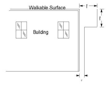
Walkable Surfaces |
12.0 Feet |
12.0 Feet |
|
6 |
Non–Walkable Surfaces |
8.0 Feet |
8.0 Feet |
Footnotes Modifying
Clearances in Table 58–1
(a) May be reduced to 20 feet provided such lead or bus wires are guarded by transformer platform flooring which extends not less than 1 foot horizontally outside the vertical planes of all such lead and bus wires.
(b) May be reduced under special conditions: Supply conductors of 750 - 7,500v see Rule 54.4–H1 .
(c) If less than 6 feet below a walkable surface must have 6 foot horizontal clearance until vertical clearance is obtained.
|
Table 58–2 Ungrounded Cases from Line Conductors (a) (b) |
||||||
|
Line Conductors |
Comm. |
0 - 750 Volts |
750 - 7500 Volts |
7500V - 22.5KV |
22.5 kV & above |
|
|
1 |
Vertical above Case |
48 in. |
3 in.(c) |
12 in.(d) |
18 in. (e) |
24 in. |
|
2 |
Vertical below Case |
48 in. |
10 in.(d) |
12 in.(d) |
18 in. (e) |
24 in. |
|
3 |
Horizontal from Case |
N/A |
6 in. |
12 in. |
18 in. |
24 in. |
Footnotes Modifying Clearances in Table 58–2
(a)
For
grounded cases see Rule 54.4–G .
(b) For clearances from connecting lead wires and cases, see Table 2, Case 17
(c)
For conductors supported by rack
construction, this dimension shall be a minimum of 4 feet.
(d)
May be reduced to 3 inches radially from
unenergized cases and hangers, provided no line conductor which is less than 12
inches horizontally from the case or hanger is less than 3 inches above the
level of the top surface of the crossarm.
(e) For transformers see Rule 54.4–D8 .
58.53
Line Switches and Line Disconnects
Line switches and line disconnects shall be located so that they are readily accessible from climbing and working spaces. Such devices or their connecting leads shall not extend into the climbing space but may extend into the working space.
A.
Clearance Between Energized Parts UnenclosedUnenclosed switches supported
on poles or pole structures shall be arranged with clearances not less than as
specified in Table 2, Case 15 between the center lines of the separate phase
units.
(1)
Vertical clearances between exposed
energized parts of line switches and line disconnects (including fused and
unfused line cutouts) and unprotected conductors of other circuits above and
below shall not be less than the clearances specified by Table 2, Cases 8 to 13
.
Clearances between
exposed parts of line switches and line disconnects (including fused or unfused
line cutouts) which are energized from the same circuit, from exposed parts of
different phases or polarities shall not be less than the clearances specified
by Table 2, Case 17.
Unenclosed switches supported
on poles or pole structures shall be arranged with clearances not less than as
specified in Table 2, Case 17 between exposed parts which are energized from
the same circuit from different phases or polarities.
B.
Clearance Between Unenergized Parts and
Unprotected Conductors
Metal switch cases and
normally Unenergized metal parts in contact therewith shall clear all
unprotected conductors, except the connecting leads, by distances as specified
in Rule 58.3-B3 for Unenergized metal parts of transformers from unprotected
conductors.
C.
Lead Wires
(2)
Lead wires shall be suitably insulated
from metal or wood cases of cutouts and switches at point of entrance
thereto.
All unprotected lead wires
including miscellaneous wiring shall clear brace, bolts and other line hardware
a distance of not less than 1.5 ˝ inches.
Where necessary at points of
entrance to cutouts and switches, lead wires of 0-5000 volts may be less than 3
inches from the surface of crossarms (Table 1, Case 9, Column C, D, and E) but
shall be not be less than 1 inch from such surfaces.
D.
Climbing and Working Space
(3)
Switches and cutouts shall
be so located that, when in either the open or closed position, all energized
parts thereof are not less than 15 or 18 inches from the centerline of pole as
required by Table 1, Case 8, and no part of such equipment shall be in the
climbing space except nonmetallic interphase shafts of gang operated switches
and their associated unbonded hardware mounted at the top of the pole. See figures 58-12 and 58-23. Such apparatus is permitted to be wholly
or in part within the working space. The clearances of 15 or 18 inches need
not apply to nonfusable pole-top switches connected to a circuit of 7,500 volts
or more, provided the switches are installed substantially in the same vertical
plane as the conductors to which they are attached, and no climbing space has
to be provided through and above the level of such switches.
D.
Indicating Position
B.
Enclosed
Switches
All enclosed switched shall
indicate clearly whether they are in the open or closed position.
FC.
Grounding (see Rule 52.7-F) Grounded
(see Rule 54.4-G)
GD.
Operating Mechanism
(1)
Grounded metal operating rods which
pass through any supply or communication conductor levels shall be
protected with a suitable insulating protective covering for a vertical
distance of 8 feet vertically above and below or 6 feet
horizontally from such levels communication conductors (including
cables) and from unprotected supply conductors. As an alternative to this provision,
(2)
Ungrounded metal operating
rods which pass through supply or communication conductor level shall:
be underground and shall
a)
have a suitable insulating link
or section installed in them, at a point as near as possible to the
switch,; and a
b) have a suitable insulating link or section installed at a point between each conductor level through which it passes.
(3)
All operating rods shall be
securely held in position by staples or straps or other a
suitable means to afford clearances as specified in Table 2, Case 18 from
conductors of circuits below the switch level.
All cables, ropes and other
flexible means of operating switches shall have insulators installed in them at
a point as close as possible to the switch and shall pass through guides to
insure their separation from conductors through which they pass.
(4) Where line switches are operated from the ground level by means of all metal control mechanisms without suitable insulating links or sections, an insulated platform shall be provided unless such operating mechanism is effectively grounded.
58.6 Time Switches, Meters, Metal Boxes, and
Other Apparatus and Associated Antennas
A.
Location and Clearances from
Transformer, Capacitor or Regulator Cases Grounded (see Rule 54.4-G)Time switches, meters and
other apparatus, including their enclosures, which extend more than 5 inches
from the surface of a pole shall not be installed on the surface of a pole
shall not be installed on the surface of a pole supporting a transformer (or
other equipment of similar dimensions), shall be not less than 4 feet above or
below the nearest part of transformer case (or other equipment), unless the
time switch, meter, etc., is installed on the side of the pole occupied by the
transformer (or other equipment).
B.
Clearance from Unprotected Conductors
Ungrounded
Time switches, meters, metal
boxes, other apparatus and associated antennas are not allowed in the climbing
space.On wood poles or structures,
all grounded metal boxes and grounded metal cases for time switches, meters, or
other apparatus shall be not less than 3 feet above or 6 feet below the level
of unprotected supply conductors. Where
it is impracticable to obtain a clearance of at least 6 feet below the level of
unprotected supply conductors of 750 volts or less, a clearance of not less
than 4 feet below such conductors will be permitted if a protective covering or
guard is provided above the grounded surface.
C.
Within 8 feet of the ground
Boxes or enclosures containing
switches, meters, or other apparatus having accessible live parts, which are
located 8 feet or less above the ground shall be effectively locked or sealed.
Metal Boxes which contain supply
or control equipment or conductors and are located 8 feet or less above the
ground shall be effectively grounded.
Final Version
Rule 58
58 Miscellaneous Equipment
58.1
Enclosed Equipment (Transformers, Capacitors, Regulators, etc.)
(1)
Multiple Units: Where more than one unit is
installed on a pole, they shall be placed on the same side of the pole.
(2)
Pole Top Extensions: Equipment shall not be supported on
pole top extensions.
EXCEPTION: Pole top extensions that conform with strength
requirements for a whole pole (see Rule
49.1–A ) may be used to support
equipment.
B.
Case and Lead Wire
Clearances (See Tables 58–1 & 58–2 )
(1)
Unprotected Lead Wire Clearances:
Unprotected vertical and lateral leads between line conductors and equipment
shall comply with Rules 54.6 and 54.4–C6 ; and with the clearances specified
in Table 1, Cases 8 and 9 ; and
Table 2, Cases 15, 16 and 17 .
Such lead wires may be installed in the working space but shall not be installed
in the climbing space.
The clearance specified in Table
1, Case 8, Columns D and E , need not apply to apparatus installed on poles
consisting of single–pole structures or on crossarms attached thereto, provided
that terminals and lead wires are not less than 6 inches from surface of pole
instead of 3 inches specified in Table 1, Case 9, Columns D and E , and have as much as
possible of the clearances specified in Table 1, Case 8, Columns D and E. No reduction of the
clearances specified in Table 1, Case
8, Columns D and E is permitted for interconnection wiring of polyphase
installations nor to any lead wire passing between pole and apparatus.
(2)
Cases above Ground: Cases of equipment supported on
poles or structures shall be not less than 17 feet above the ground except that
in areas which are not in any way accessible to vehicles, the clearance of cases
above ground may be less than 17 feet provided all cases which are less than 8
feet above ground shall be effectively grounded.
(3)
From Hardware: Equipment cases, hangers, and other
metal parts in contact therewith shall clear through bolts, arm braces of metal,
and other hardware elements, by not less than 1.5 inches; except that such cases
and hangers shall clear crossarm braces and crossarm through bolts by not less
than 1 inch air–gap distance and 1.5 inch creepage distance.
The minimum clearance of 1.5 inches need not apply to through bolts in
metallic contact with equipment cases or metal parts thereof nor to through
bolts supporting heel arms, provided the portion of such through bolts extending
into the climbing space is covered with non–conducting material as specified in
Rule 22.2 .
(4)
From Guys: Equipment cases and their hangers shall
not be less than 4 inches from all portions of guys which are 6 inches or more
from the surface of poles or crossarms at the guy attachments. Such cases and
hangers shall not be less than 1.5 inches from all portions of guys which are
within 6 inches of the surface of poles or crossarms at the guy
attachment.
C.
Equipment Cutouts or Other Equipment Disconnecting
Devices
Equipment cutouts, fuses, disconnects or switches shall be located
so that they are readily accessible from climbing and working spaces. Such
devices or their connecting leads shall not extend into the climbing space, but
may extend into the working space.
The vertical clearance between equipment cutouts, fuses, disconnects or
switches and unprotected conductors of other circuits below shall not be less
than the clearances required between conductors as specified in Table 2, Cases 8 to 13 .
The horizontal clearance between equipment cutouts, fuses, disconnects or
switches and unprotected conductors of different phase or polarity shall not be
less than the clearances specified in Table 2, Case 17 .
The provisions of this rule shall not apply to partial underground
distribution systems.
D.
Ungrounded Case Clearances from Line Conductors (See Table 58–2 )
E. Grounded Case Clearances from Line Conductors (See Rule 54.4–G )
F.
Bonding
Cases of equipment may be bonded together but shall not be bonded to
cutouts, metal pins or deadend
hardware.
|
Unprotected Bus and Lead Wire Clearances |
|||
|
Case |
Nature of Clearance |
Clearances Required |
|
|
750 Volts - 22.5 kV |
22.5 kV & above |
||
|
Above Ground |
|
|
|
|
1 |
Single Pole Structure |
22.5 Feet |
27.0 Feet |
|
2 |
Two or More Pole Structure |
22.5 Feet (a) |
27.0 Feet (a) |
|
From Buildings - Horizontal |
|
|
|
|
3 |
With Windows, Fire Escapes, etc. |
6.0 Feet (b) |
6.0 Feet |
|
4 |
Without Windows, Fire Escapes, etc. |
1.0 Foot (c) |
1.0 Foot |
|
From Building - Vertical above |
|
|
|
|
5 |
Walkable Surfaces |
12.0 Feet |
12.0 Feet |
|
6 |
Non–Walkable Surfaces |
8.0 Feet |
8.0 Feet |
Footnotes Modifying Clearances in
Table 58–1
(a) May be reduced to 20 feet provided
such lead or bus wires are guarded by transformer platform flooring which
extends not less than 1 foot horizontally outside the vertical planes of all
such lead and bus wires.
(b) May be reduced under special conditions: Supply conductors of 750 - 7,500v see Rule 54.4–H1 .
(c) If less than 6 feet below a walkable surface must
have 6 foot horizontal clearance until vertical clearance is obtained.
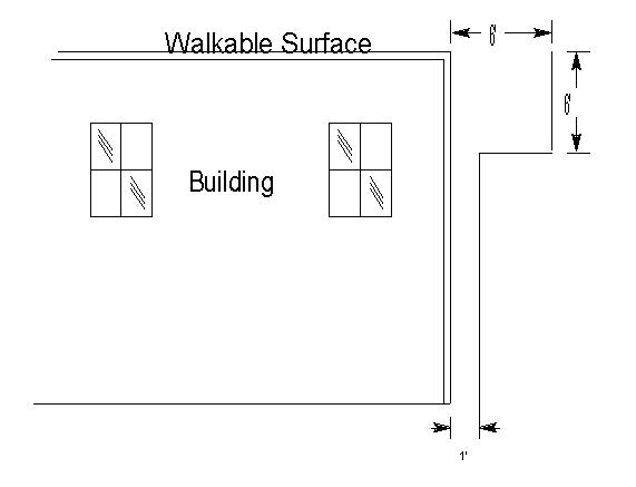
|
Ungrounded Cases from Line Conductors (a) (b) |
||||||
|
Line Conductors |
Comm. |
0 - 750 Volts |
750 - 7500 Volts |
7500V - 22.5KV |
22.5 kV & above |
|
|
1 |
Vertical above Case |
48 in. |
3 in.(c) |
12 in.(d) |
18 in. (e) |
24 in. |
|
2 |
Vertical below Case |
48 in. |
10 in.(d) |
12 in.(d) |
18 in. (e) |
24 in. |
|
3 |
Horizontal from Case |
N/A |
6 in. |
12 in. |
18 in. |
24 in. |
Footnotes Modifying Clearances in Table 58–2
(a) For grounded cases see Rule 54.4–G .
(b) For clearances from connecting lead wires and cases, see Table 2, Case 17 .
(c) For conductors supported by rack construction, this dimension shall be a minimum of 4 feet.
(d) May be reduced to 3 inches radially from unenergized cases and hangers, provided no line conductor which is less than 12 inches horizontally from the case or hanger is less than 3 inches above the level of the top surface of the crossarm.
(e)
For transformers see Rule 54.4–D8
.
58.2
Transformers
A. Grounding or Bonding
(1) Grounding of Windings: Where transformer
windings are grounded, they shall be effectively grounded. Where the secondary
system is grounded at any point, the grounded conductor shall be run to each
service.
(2) Location of Transformer Winding Grounds:
Transformer ground connections shall be provided at one of the following
locations:
At the transformer pole or
At a pole adjacent to the transformer pole.
Transformer
ground connections other than those occurring on common primary and secondary
grounded neutral systems shall have an ampacity not less than that of No. 6 AWG
copper wire.
Where a common primary and secondary grounded neutral system is used, ground
connections shall conform to the requirements of Rule 59.4–A .
(3)
Transformer Case Grounding or Bonding: (See Rule 54.4–G for Grounded Equipment Clearances)
Transformers shall not be supported on metal poles or metal supports
in contact with the ground unless the cases are securely bonded to the metal
poles or parts of structures in contact with the ground and such poles or
structures are effectively grounded. Transformers installed on metal mounting
brackets shall not extend beyond the vertical plane through the centerline of
the pole.
Where transformer cases are bonded, the case bonding system shall not be
electrically connected to any unassociated hardware or to other
bonds.
B. Connections between
Windings
Any metallic connection between the primary and secondary windings
of a distribution transformer (as in common neutral systems) shall be made
externally and not within the transformer
case.
58.3
Line Switches and Line Disconnects
Line switches and line disconnects shall be located so that they are
readily accessible from climbing and working spaces. Such devices or their
connecting leads shall not extend into the climbing space but may extend into
the working space.
A. Unenclosed
(1)
Vertical clearances between exposed energized
parts of line switches and line disconnects (including fused and unfused line
cutouts) and unprotected conductors of other circuits above and below shall not
be less than the clearances specified by Table 2, Cases 8 to 13 .
Clearances between exposed parts of line switches and line disconnects
(including fused or unfused line cutouts) which are energized from the same
circuit, from exposed parts of different phases or polarities shall not be less
than the clearances specified by Table 2, Case 17 .
(2)
Lead wires shall be suitably insulated from cases of
cutouts and switches at points of entrance thereto.
All unprotected lead wires including miscellaneous wiring shall clear braces,
bolts and other line hardware a distance of not less than 1.5”.
Where necessary at points of entrance to cutouts and switches, lead wires of
0 - 5,000 volts may be less than 3 inches from the surface of crossarms ( Table 1, Case 9, Columns C, D and E
) but shall not be less than 1 inch from such surfaces.
(3)
Switches and cutouts shall be so located that, when in
either the open or closed position, all energized parts thereof are not less
than 15 or 18 inches from the centerline of pole as required by Table 1, Case 8 , and no part of
such equipment shall be in the climbing space except nonmetallic interphase
shafts of gang operated switches and their associated unbonded hardware mounted
at the top of the pole (see Figures 58–2 and 58–3 ). Such apparatus is permitted to be within the working
space. The clearance of 15 or 18 inches need not apply to nonfusable pole–top
switches provided the switches are installed substantially in the same vertical
plane as the conductors to which they are attached, and no climbing space has to
be provided through and above the level of such
switches.
B. Enclosed Switches
All enclosed switches shall indicate clearly whether they are in the
open or closed position.
C. Grounded (See Rule 54.4–G )
(1) Grounded metal operating rods which pass through
any supply or communication conductor level shall be protected with a suitable
protective covering for a vertical distance of 8 feet above and below or 6 feet
horizontally from such levels.
(2) Ungrounded metal operating rods which pass through only supply or communication conductor level shall:
a) Have a suitable insulating link or section
installed at a point as near as possible to the switch; and
b) Have a suitable insulating link or section installed at a
point between each conductor level through which it
passes.
(3)
All operating rods shall be
securely held in position by a suitable means to afford clearances as specified
in Table 2, Case 18 from
conductors of circuits below the switch level.
(4) Where line switches are operated from the ground level by
means of all–metal control mechanisms without suitable insulating links or
sections, an insulated platform shall be provided unless such operating
mechanism is effectively
grounded.
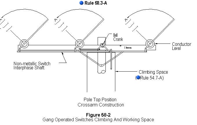
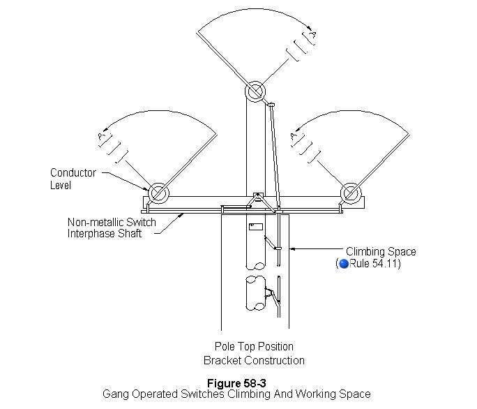
58.4
Traffic Signals
Traffic signals supported on overhead suspensions shall be treated
as specified in the following rules:
A. Messenger and Span Wire Clearances
The suspension messenger or span wire of all traffic signals shall
be installed to afford the clearances prescribed for span wires in Table 1, Column A , and Table 2, Column A
.
B. Lead Wires
Lead wires of 0 - 750 volts to traffic signals supported on
messengers may be less than the clearances above ground specified in Table 1, Column D, Cases 2 and 3
provided they are maintained at a clearance above ground as specified in Table 1, Column A, Cases 2 and 3 for
the messenger on which they are supported.
C. Clearance
above Thoroughfares
Traffic signals supported by span wires and supplied from circuits
of 0 - 750 volts shall have a clearance of not less than 14 feet vertically
above thoroughfares over which they are suspended (see Figure 58–4 ) except
that where any thoroughfare is used by railroads, street railways, trolley coach
lines and double deck motor coaches, clearance not less than the following shall
be maintained:
|
Conveyance Using Thoroughfare |
Minimum Clearance of Signalabove Thoroughfare |
|
Street railways and coach lines operated by overhead trolley |
Height of trolley conductor plus 1 foot (a) |
|
Railroads which transport freight cars |
25 Feet (b) |
|
Double deck motor coaches |
18 Feet |
(a) May be
reduced to 14 feet if signal is more than 8 1/2 feet from nearest trolley
contact conductor and if signal is maintained not less than 1 foot radially from
trolley span wires.
(b) May be reduced to 14 feet if
signal is more than 8 1/2 feet from centerline of track.
Traffic signals
supplied directly (without protective transformers) from circuits classified in
excess of 750 volts shall be installed with clearances as prescribed for street
lighting equipment.
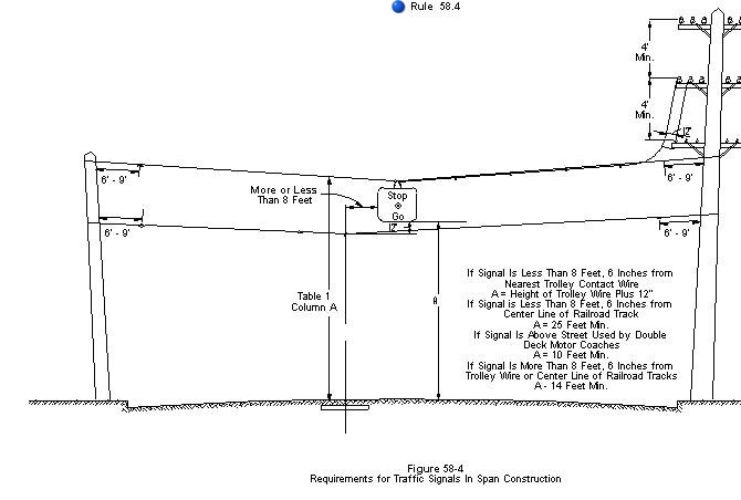
58.5
Street Lighting Equipment
A. Circuit Voltage
Constant current series lighting circuits supplied from transformers
or devices having an open circuit output voltage of more than 750 volts, except
those circuits supplied from transformers or devices having a normal full-load
output voltage of 750 volts or less which transformers are equipped with
effective protective devices to prevent the continued existence of open-circuit
voltage on the circuit, shall be classified as circuits of more than 750
volts.
Constant current series lighting circuits which conform to the specifications
for circuits of 0-750 volts may be installed and treated as circuits of more
than 750 volts provided any circuit so treated in any respect is consistently so
treated throughout its entirety.
B. Clearances
(1)
Above Ground: No part of street lighting
equipment shall be less than 20 feet above thoroughfares except for lamps
supported on brackets or fixtures which do not extend more than 48 inches from
the face of pole or street side of curb, in which case the clearance may be
reduced to 15 feet, provided the voltage does not exceed 750 volts (see Fig. 58-5 ).
(2)
Above Railways and Trolley Lines: No part of
street lighting equipment which is less than 8 1/2 feet horizontally from
centerline of tracks of railroads not operated by overhead trolley shall be less
than 25 feet above such tracks.
No part of street lighting equipment which is less than 8 1/2 feet
horizontally from the centerline of tracks or from the nearest trolley contact
conductor shall be less than 4 feet above the level of the trolley contact
conductor or less than 23 feet or 26 feet above running surfaces used by trolley
cars or coaches depending upon the location of the contact conductors as
required by Rule 74.4-B1 .
Those parts of street lighting equipment which are 8 1/2 feet or more
horizontally from the centerline of any railroad track or any trolley contact
conductor shall not be less than 20 feet above the surface of the thoroughfare,
except as provided in Rule 58.5-B1 (see Fig. 58-5 ).
(3)
From Conductors:
a) Messengers and Cables: All parts of
street light drop wires, street lamps, and their supporting fixtures (including
rods, braces and guys) shall not be less than 1 foot above or 2 feet below the
level of messengers or conductors supported by messengers. These vertical
clearance requirements shall not apply to those parts of such street lighting
equipment which are 2 feet or more horizontally from the vertical plane of
messengers, conductors supported by messengers, and metal boxes.
b)
Conductors Not Supported by Messengers: All parts
of street light drop wires, street lamps, and their supporting fixtures
(including rods, braces and guys) shall not be less than 1 foot radially from
all unprotected conductors not supported on messengers (including lead wires and
taps) except the lead wires supplying the street lamps within 24 inches of their
points of entrance to the street lighting equipment.
(4)
From Poles: All exposed metal parts of lamps and all such
parts of their supports, unless insulated from the parts carrying current, shall
be maintained not less than 20 inches from the surface of wood–poles, except at
pole tops. This rule shall not apply if the voltage of the circuit from which
the lamp is supplied does not exceed 750 volts.
C. Lead
Wires
Unprotected conductors from one level on a pole or structure to
another level or to street lighting equipment shall not pass within a climbing
or working space, and shall not pass through any other circuit except between
pole pin positions.
Such unprotected conductors shall clear the conductors of other circuits by
distances as specified in Rule 54.6-A .
Where the distance between levels is in excess of 12 feet and such
unprotected conductors pass between the pole pair of conductors of any other
circuit, additional supports shall be installed so that the maximum length of
conductor between supports is not more than 12 feet.
Unprotected leads to street lighting equipment shall be maintained at not
less than the clearances above railroads, thoroughfares and ground specified for
street lighting equipment in Rule 58.5-B
.
D. Insulators In Supports
Where a street lighting fixture is supported by a span wire, strain
insulators shall be inserted in the span wire on both sides of the fixture not
more than 9 feet nor less than 6 feet from the structures supporting the span
wire; except that, where such span wire is used as a trolley for the purpose of
drawing the fixture to the pole, the strain insulator at the service end may be
located a distance not less than 15 inches from the centerline of pole.
Where metallic ropes or chains are used for the suspension of street lamps,
said ropes or chains shall be effectively insulated from current carrying parts
of equipment and of such length that when the lamp is in its normal position the
lower end of the chain or rope will not be less than 8 feet from the ground, or
a strain insulator shall be inserted in the free end of the rope or chain at a
point not less than 7 1/2 feet from the ground when the lamp is in its normal
position. Metallic ropes or chains shall be arranged so that they do not
establish a metallic conducting path around a span wire sectionalizing
insulator. In case this construction will not permit the lamp to be lowered
sufficiently for trimming purposes, a nonmetallic rope shall be used (see Fig. 58-5
).
E. Lighting Units On Transformer or Switch
Poles
Lighting units installed in the proximity of a transformer or switch
shall have the following minimum radial clearances:
|
1) Lighting units above |
4 feet |
|
2) Lighting units below |
1 foot |
F. EXCEPTIONS
Lighting units supported on ornamental posts and supplied from
underground sources are not included
herein.
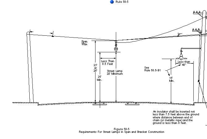
58.6
Time Switches, Meters, Metal Boxes, Other Apparatus and Associated
Antennas
A. Grounded (See Rule
54.4–G )
B. Ungrounded
Time switches, meters, metal boxes, other apparatus and associated
antennas are not allowed in the climbing space.
C. Within
8 Feet of the Ground
Boxes or enclosures containing switches, meters, or other apparatus
having accessible live parts, which are located 8 feet or less above the ground
shall be effectively locked or sealed.
Metal boxes which contain supply or control equipment or conductors and are
located 8 feet or less above the ground shall be effectively
grounded.